
-
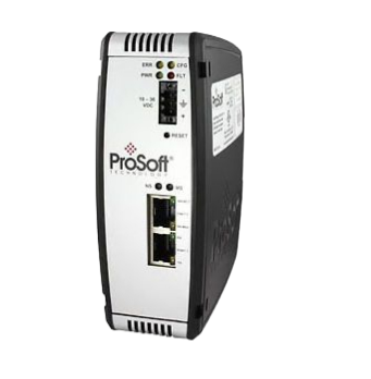
Prosoft PLX51-PBS PROFIBUS DP Slave to EtherNet/IP™, Modbus® TCP/IP, or Modbus® Serial Gateway
-
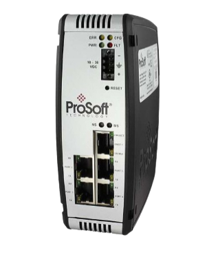
Prosoft PLX51-PBM PROFIBUS DP Master/Slave to EtherNet/IP™, Modbus TCP/IP®, or Modbus® Serial Gateway
-
Prosoft PLX51-DLplus-232 Data Logger Plus
-
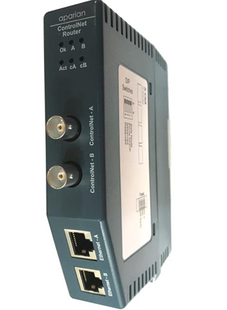
Prosoft A-CNR ControlNet Router
-
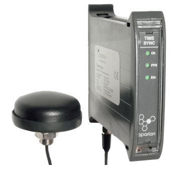
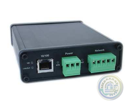
Prosoft A-TSM/B Time Sync Module
-
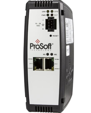
Prosoft PLX51-HART-4O 4 Channel HART Output Module
-
Prosoft PLX51-PBS PROFIBUS DP Slave to EtherNet/IP™, Modbus® TCP/IP, or Modbus® Serial Gateway
-
Prosoft PLX51-PBM PROFIBUS DP Master/Slave to EtherNet/IP™, Modbus TCP/IP®, or Modbus® Serial Gateway
-
Prosoft PLX51-DLplus-232 Data Logger Plus
-
Prosoft A-CNR ControlNet Router
-
Prosoft A-TSM/B Time Sync Module
-
Prosoft A-XGPS XPosition Module
-
Prosoft PLX32-EIP-104 EtherNet/IP to IEC 60870-5-104 Gateway
-
Prosoft PLX32-MBTCP-104 Modbus TCP/IP to IEC 60870-5-104 Gateway
-
Prosoft A-PAL/B PA Link Series B PA Gateway
-
Prosoft A-DH485R/B DH485 Router
-
Prosoft PLX51-DNPS Distributed Network Protocol (DNP3) Gateway
-
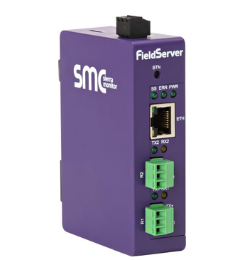
Prosoft PS-QS-2x10-F Universal QuickServer Gateway
-
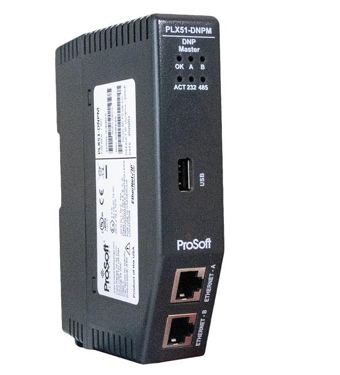
Prosoft PLX51-DNPM Distributed Network Protocol (DNP3) Master Gateway
-
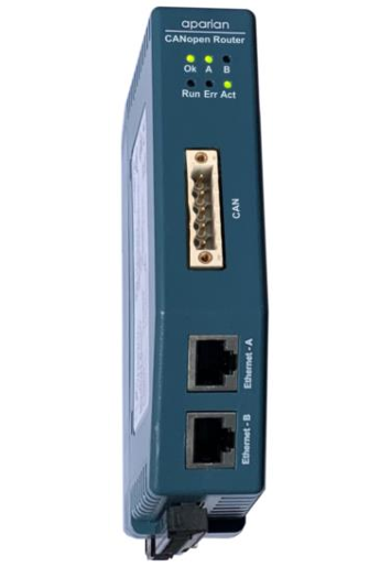
Prosoft A-CANOR/B CANopen Router/B
-
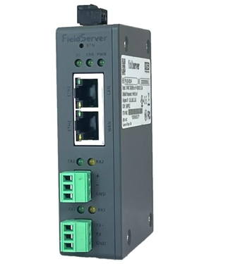
Prosoft PS-QS-3x10-F Universal QuickServer Gateway Dual Ethernet Port
-
Prosoft EtherNet/IP™ to Remote I/O or DH+ Gateway AN-X4-AB-DHRIO
-
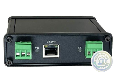
Prosoft A-DNTR/B DeviceNet Router Series B
-
Prosoft A-J1939R/B J1939 Router/B
-
Prosoft PS-QS-1x11-F LonWorks QuickServer Gateways
-
Prosoft AN-X3-GENI EtherNet/IP™ to GE Genius™ I/O Gateway
-
Prosoft A-FFL/B FOUNDATION™ Fieldbus H1 Master for EtherNet/IP™ and Modbus® TCP
-
Prosoft ELX3 Industrial Edge Gateway
-
Prosoft A-CFR ControlNet Fiber Repeater
-
Prosoft A-CANBR/B CAN Bus Router/B
-
Prosoft EtherNet/IP™ to Reliance AutoMax DCS or Remote I/O Gateway, non-CE AN-X-AMX
-
Meggitt Flow shutoff valve C327935
-
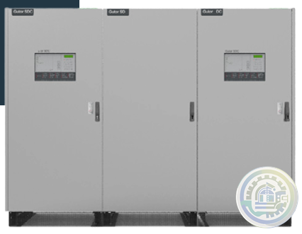
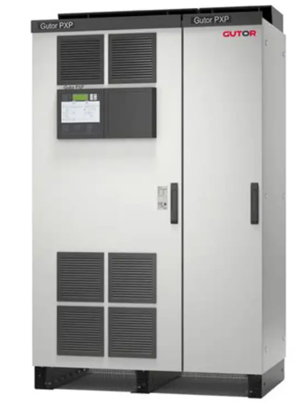
GUTOR PDW AC UPS
-
GUTOR SDC RECTIFIER / BATTERY CHARGER
-
GUTOR WEW / WDW INVERTER SYSTEM
-
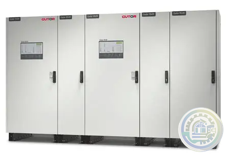
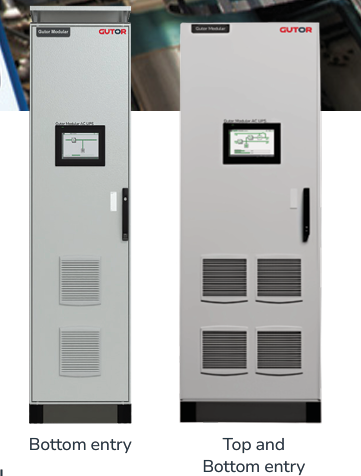
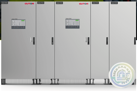
GUTOR MODULAR AC UPS SYSTEM
-
GUTOR SPARE PARTS Minimize downtime of your UPS system
-
GUTOR PDW AC UPS
-
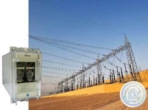
GE MVAJM High Speed Tripping and Control Relays
-
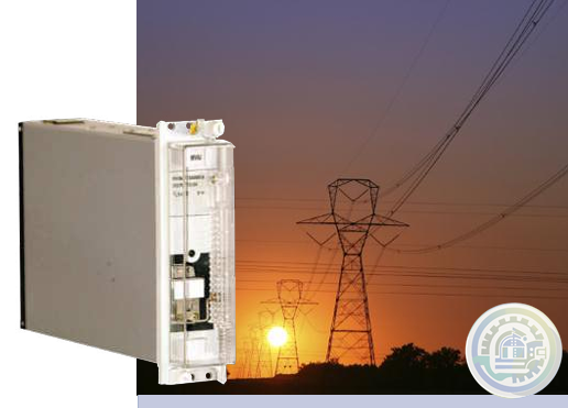
GE MVAJ 31 Tripping and Control Relays
-
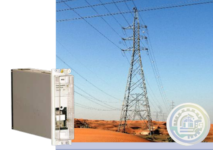
GE MVAJ 11 to 34 Tripping and Control Relays
-
GE MVAJ 05/10/20 Tripping and Control Relays
-
ZYGO Guardian™ Industrial Enclosure
-
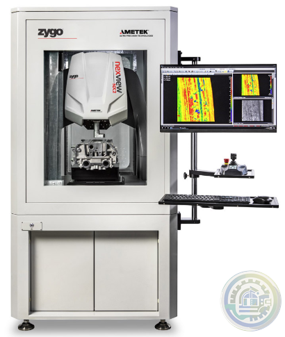
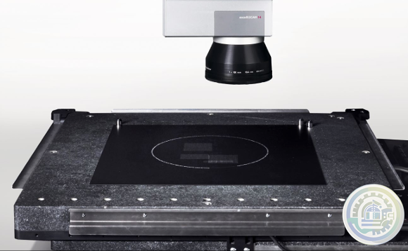
ZYGO Nexview™ 650: Large Format Inspection & Metrology
-
ZYGO NewView™ 9000 with Coherence Scanning Interferometry Technology
-
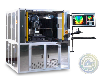
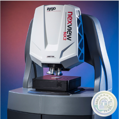
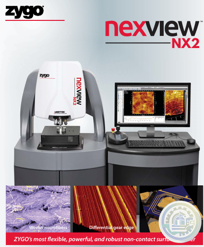
ZYGO Nexview™ NX2 3D Optical Profiler
-
ZYGO’s most flexible, powerful, and robust non-contact surface profiler
-
Pioneer Magnetics MID VOLTAGE 12V TO 60V AC TO DC SINGLE OUTPUT
-
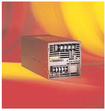
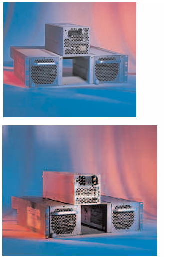
Pioneer Magnetics 3U POWERSHELF PRODUCT SERIES
-
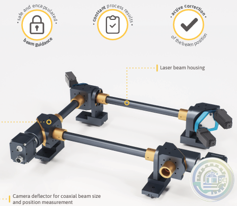
Scanlab Beam Alignment Module – BAM-G1
-
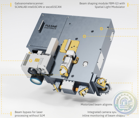
Scanlab FlexibleBeamShaper FBS-G3
-
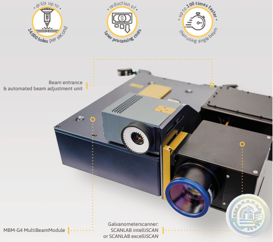
Scanlab MultiBeamScanner MBS-G4
-
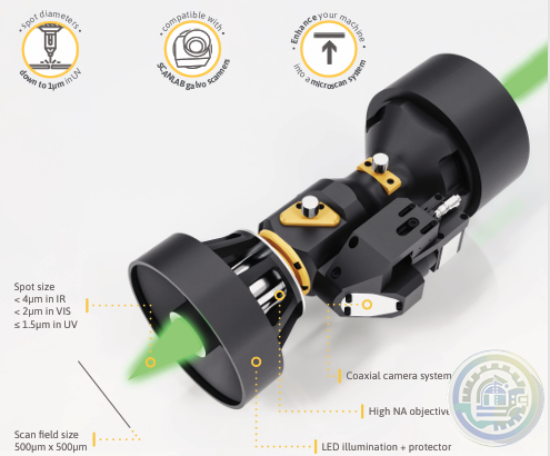
Scanlab Microscan Extension MSE-G2
-
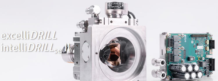
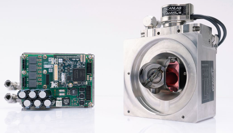
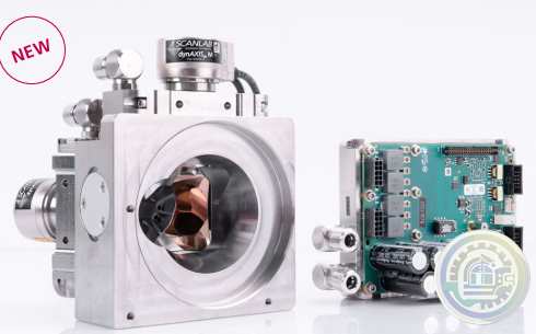
Scanlab excelliDRILL and intelliDRILLse II
-
Scanlab intelliDRILLse II – smart drilling
-
Scanlab excelliDRILL – high performance drilling
-
Scanlab XL SCAN SCANmotionControl
-
Scanlab precSYS micromachining sub system
-
Scanlab WelDYNA Scan Head
-
Scanlab Collimation Module
-
Scanlab intelliWELD 3D scan systems
-
MOOG ELECTROHYDROSTATIC PUMP UNIT WITH INTERNAL GEAR PUMP (EPU-G)
-
MOOG Electrohydrostatic Pump Unit
-
MOOG ENERGY MANAGEMENT SYSTEM (EMS) FOR EAS
-
MOOG ESU-C Energy Management System
-
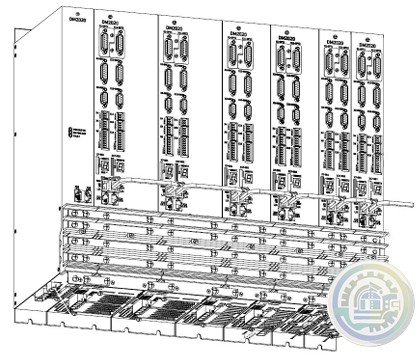
MOOG DE2020 Energy Management System
-
MOOG Silencer® Series Drive Electronics 2-Quadrant Speed Controllers for Brushless Motors
-
MOOG MSD Modular Multi-Axis Servo Drive System
-
MOOG DM2020 Drive System Overview
-
MOOG DM2020 Digital Multi-Axis Servo Drive
-
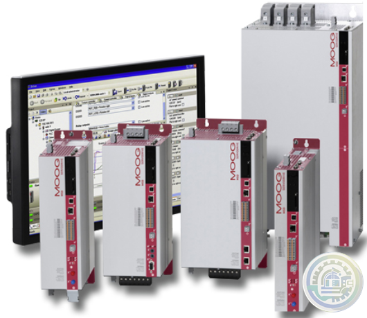
MOOG DS2020 Digital Single-Axis Servo Drive
-
MOOG Reconfigurable Actuation Control Unit Family
-
MOOG 2-channel Electronic Control Unit (ECU)
-
Bachmann CMS – Modules, Measuring Systems and Sensors
-
Bachmann CMS – Condition Monitoring System
-
Bachmann M-JVIS, M-JSYS Java Libraries
-
Bachmann CFA200 MLC CFast Memory for HMI devices only
-
Bachmann CFA200 SLC CFast Memory Memory card
-
Bachmann Operator Terminal Systemsoftware
-
Bachmann Operator Terminal System Software
-
Bachmann Die Operator Terminals der OT1300-Produktserie vereinen
-
Bachmann Das Web Terminal OT1200
-
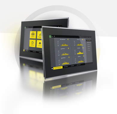
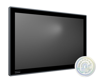
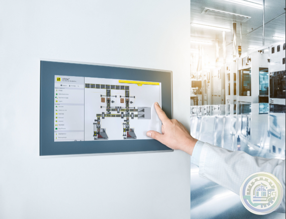
Bachmann OT1200 Web Terminal Panel PC Series
-
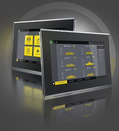
Bachmann OT1300 Operator Terminal Panel PC Series
-
Bachmann PPC1200 ECO series panel PCs
-
Bachmann Panel PCs The optimum operator terminal for every application
-
Prosoft PLX31-EIP-MBS EtherNet/IP™ to Modbus® Serial Communication Gateway
-
Prosoft PLX31-EIP-MBS4 EtherNet/IP to Modbus Serial 4 Port
-
Prosoft PLX31-EIP-MBTCP EtherNet/IP™ to Modbus® TCP/IP Communication Gateway
-
Prosoft AN-X-TI EtherNet/IP to Texas Instruments Remote I/O Master Gateway, non-CE
-
Moog Gimbal Control Electronics (GCE)
-
Moog Downhole Motor Controllers
-
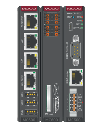
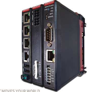
Moog Main CPU 6031 CPU MODULES
-
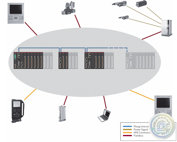
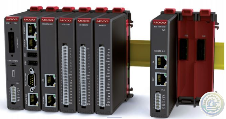
Moog Machine Controller (MC Series 600)
-
MOOG Machine Controllers Series 600 (MC600)
-
MOOG MC600 Series Machine Controller
-
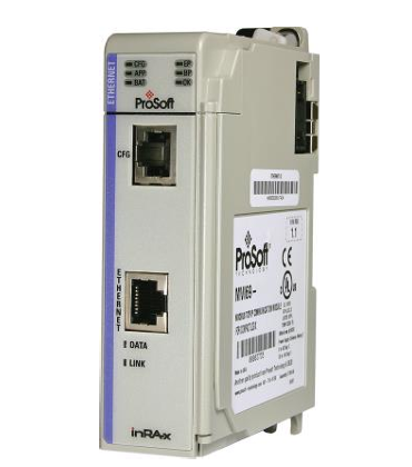
Prosoft MVI69-DFNT EtherNet/IP Client/Server Communication Module for CompactLogix
-
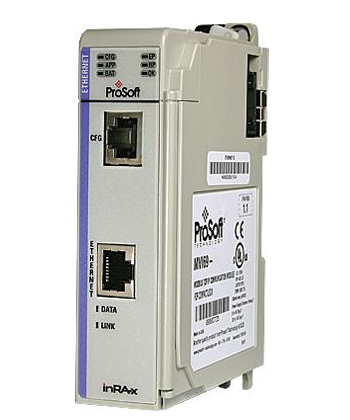
Prosoft MVI69-EGD GE Ethernet Global Data Communication Module
-
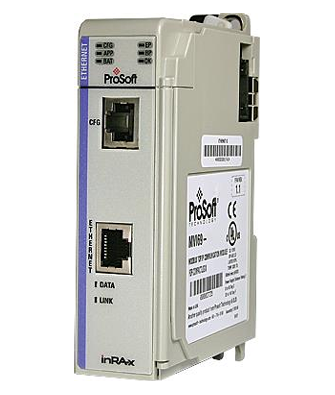
Prosoft MVI69-S3964R Siemens 3964R Protocol Communication Module
-
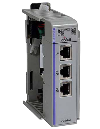
Prosoft MVI69-FLN FA Control Network Communication Module
-
Prosoft MVI69L-MBS Modbus Serial Lite Communication Module
-
Prosoft MVI69L-MBTCP Modbus TCP/IP Lite Communication Module
-
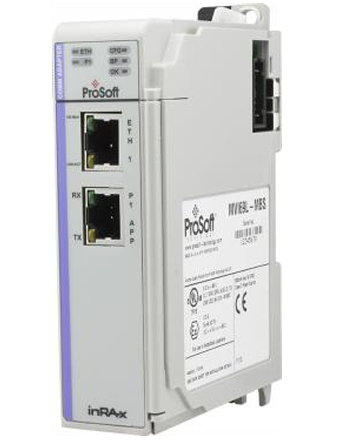
Prosoft MVI69E-LDM Linux Development Module for CompactLogix™
-
Prosoft ILX69-PBS PROFIBUS DPV1 Slave for CompactLogix
-
Prosoft ILX69-PBM PROFIBUS DPV1 Master for CompactLogix
- Other brands
- WAGO
- ICS Triplex
- IBA
- Hirschmann
- Bachmann
- Alfa Laval
- Baldor
- Glassman
- Johnson Controls
- Watlow
- ZYGO
- ADVANCED
- KEBA
- Bristol Babcock
- Rolls-Royce
- Aerotech
- Pioneer Magnetics
- Basler
- SAACKE
- BENDER
- Kollmorgen
- MEGGITT
- METSO
- MITSUBISHI
- MTL
- HIMA
- Siemens
- BACHMANN
- AMAT
- DEIF
- DELTATAU
- EATON
- ELAU
- LAM
- SCHNEIDER
- Advantest
- ABB
- GE
- Emerson
- Motorola
- A-B
- KUKA
- Abaco
- HITACHI
- SST
- Vibro-Meter
- Rexroth
- Prosoft
- DFI
- Scanlab
- Reliance
- Parker
- Woodward
- MOOG
- NI
- FOXBORO
- Triconex
- Bently
- ALSTOM
- YOKOGAWA
- B&R
- UNIOP
- KONGSBERG
- Honeywell
- Omron
- CTI
- EPRO


- Tell:+86-18144100983
- email:kongjiangauto@163.com
- Application:wind/ petroleum/ chemical/ natural gas/ Marine/ mining/ aviation/ electronics/ steel/ nuclear power/ electric power/ coking/ air separation and so on
- Series:PLC/ DCS/ servo/ analog/ Ethernet/ digital/ redundant module/ tension system/ excitation/ generator management/ human-machine interface/ detection card/ sensor/ AC drive/ etc
This manual describes the ProTech® electronic two-out-of-three Overspeed
Protection System. The manual explains the operation and gives the
configuration procedures for the system. This manual does not contain
instructions for the operation of the complete turbine system. For turbine- or
plant-operating instructions, contact the plant-equipment manufacturer.
Before doing any installation, maintenance, adjustments, or configuration on the
ProTech 203 system, read manual 82715. Guide for Handling and Protection:
Electronic Controls, Printed Circuit Boards, Modules.
Table 4-3 gives the maximum overload
protection for supply mains connected to any single or redundant pair of MicroNet Plus main power
supplies. It is not recommended that both MicroNet Plus main power supplies of a redundant pair be
connected to a single source, since failure of that source would disable the system.
Multiple chassis systems using MicroNet Plus power supplies may have power supplies of the same
model, but in different chassis, connected to the same source. In this case, each branch to a chassis
must have its own overcurrent protection sized according to Table 4-3. and the power source must be
sized for the sum of the branches.

In the event that on supply needs to be replaced, the recommended method for changing
Power Modules is with the power off (to the module being removed and the module being inserted).
The system will tolerate this “cold swap” method without failure.
Each main power supply has four LEDs to indicate power supply health (OK, Input Fault,
Overtemperature, and Power Supply Fault).
See MicroNet Plus Power Supply Troubleshooting (Section 5.5) for a description of the LED indications.
Input power connections are made to the power supply through a plug/header assembly on the front of
the power supply.
| User name | Member Level | Quantity | Specification | Purchase Date |
|---|


-
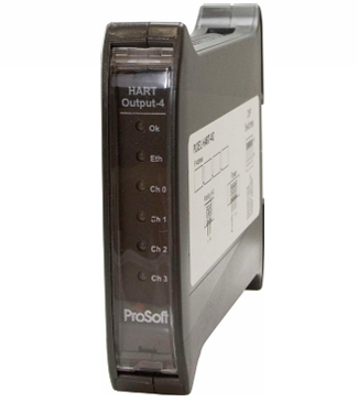 Prosoft PLX51-HART-4O 4 Channel HART Output Module
 -
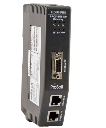 Prosoft PLX51-PBS PROFIBUS DP Slave to EtherNet/IP™, Modbus® TCP/IP, or Modbus® Serial Gateway
 -
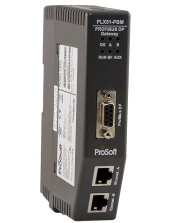 Prosoft PLX51-PBM PROFIBUS DP Master/Slave to EtherNet/IP™, Modbus TCP/IP®, or Modbus® Serial Gateway
 -
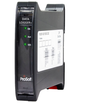 Prosoft PLX51-DLplus-232 Data Logger Plus
 -
 Prosoft A-CNR ControlNet Router
 -
 Prosoft A-TSM/B Time Sync Module
 -
 Prosoft A-XGPS XPosition Module
 -
 Prosoft PLX32-EIP-104 EtherNet/IP to IEC 60870-5-104 Gateway
 -
 Prosoft PLX32-MBTCP-104 Modbus TCP/IP to IEC 60870-5-104 Gateway
 -
 Prosoft A-PAL/B PA Link Series B PA Gateway
 -
 Prosoft A-DH485R/B DH485 Router
 -
 Prosoft PLX51-DNPS Distributed Network Protocol (DNP3) Gateway
 -
 Prosoft PS-QS-2x10-F Universal QuickServer Gateway
 -
 Prosoft PLX51-DNPM Distributed Network Protocol (DNP3) Master Gateway
 -
 Prosoft A-CANOR/B CANopen Router/B
 -
 Prosoft PS-QS-3x10-F Universal QuickServer Gateway Dual Ethernet Port
 -
 Prosoft EtherNet/IP™ to Remote I/O or DH+ Gateway AN-X4-AB-DHRIO
 -
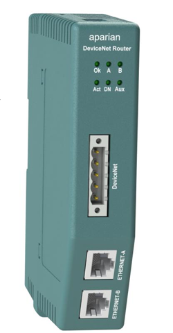 Prosoft A-DNTR/B DeviceNet Router Series B
 -
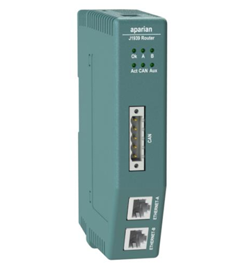 Prosoft A-J1939R/B J1939 Router/B
 -
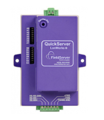 Prosoft PS-QS-1x11-F LonWorks QuickServer Gateways
 -
 Prosoft AN-X3-GENI EtherNet/IP™ to GE Genius™ I/O Gateway
 -
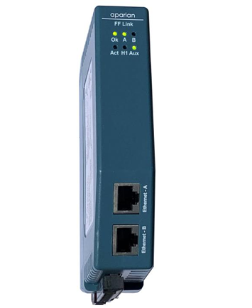 Prosoft A-FFL/B FOUNDATION™ Fieldbus H1 Master for EtherNet/IP™ and Modbus® TCP
 -
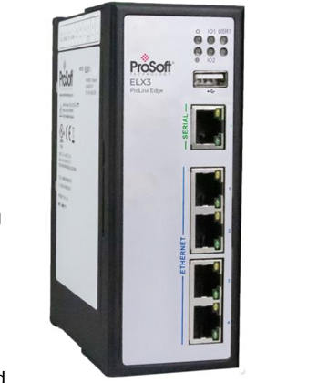 Prosoft ELX3 Industrial Edge Gateway
 -
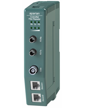 Prosoft A-CFR ControlNet Fiber Repeater
 -
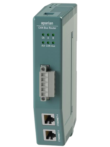 Prosoft A-CANBR/B CAN Bus Router/B
 -
 Prosoft EtherNet/IP™ to Reliance AutoMax DCS or Remote I/O Gateway, non-CE AN-X-AMX
 -
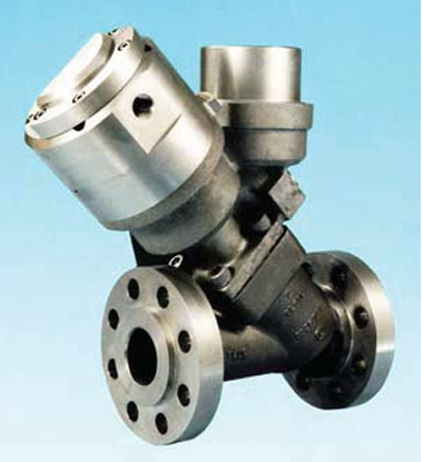 Meggitt Flow shutoff valve C327935
 -
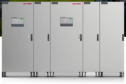 GUTOR PDW AC UPS
 -
 GUTOR SDC RECTIFIER / BATTERY CHARGER
 -
 GUTOR WEW / WDW INVERTER SYSTEM
 -
 GUTOR MODULAR AC UPS SYSTEM
 -
 GUTOR SPARE PARTS Minimize downtime of your UPS system
 -
 GUTOR PDW AC UPS
 -
 GE MVAJM High Speed Tripping and Control Relays
 -
 GE MVAJ 31 Tripping and Control Relays
 -
 GE MVAJ 11 to 34 Tripping and Control Relays
 -
 GE MVAJ 05/10/20 Tripping and Control Relays
 -
 ZYGO Guardian™ Industrial Enclosure
 -
 ZYGO Nexview™ 650: Large Format Inspection & Metrology
 -
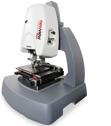 ZYGO NewView™ 9000 with Coherence Scanning Interferometry Technology
 -
 ZYGO Nexview™ NX2 3D Optical Profiler
 -
 ZYGO’s most flexible, powerful, and robust non-contact surface profiler
 -
 Pioneer Magnetics MID VOLTAGE 12V TO 60V AC TO DC SINGLE OUTPUT
 -
 Pioneer Magnetics 3U POWERSHELF PRODUCT SERIES
 -
 Scanlab Beam Alignment Module – BAM-G1
 -
 Scanlab FlexibleBeamShaper FBS-G3
 -
 Scanlab MultiBeamScanner MBS-G4
 -
 Scanlab Microscan Extension MSE-G2
 -
 Scanlab excelliDRILL and intelliDRILLse II
 -
 Scanlab intelliDRILLse II – smart drilling
 -
 Scanlab excelliDRILL – high performance drilling
 -
 Scanlab XL SCAN SCANmotionControl
 -
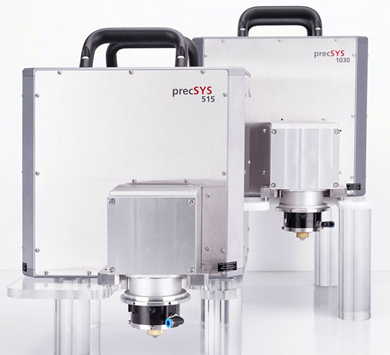 Scanlab precSYS micromachining sub system
 -
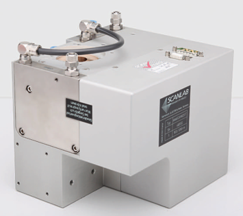 Scanlab WelDYNA Scan Head
 -
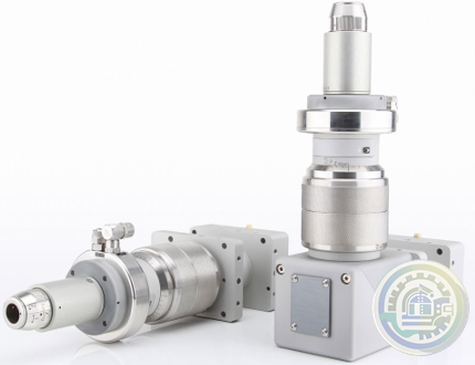 Scanlab Collimation Module
 -
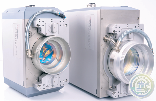 Scanlab intelliWELD 3D scan systems
 -
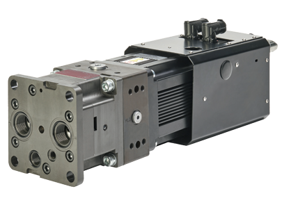 MOOG ELECTROHYDROSTATIC PUMP UNIT WITH INTERNAL GEAR PUMP (EPU-G)
 -
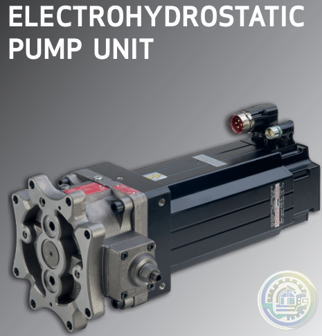 MOOG Electrohydrostatic Pump Unit
 -
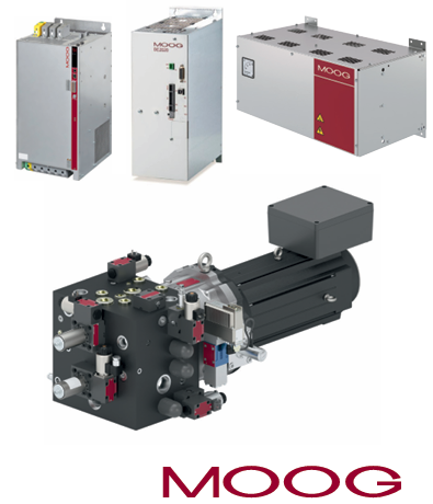 MOOG ENERGY MANAGEMENT SYSTEM (EMS) FOR EAS
 -
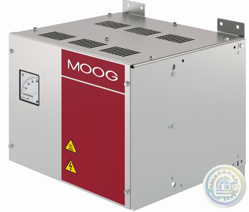 MOOG ESU-C Energy Management System
 -
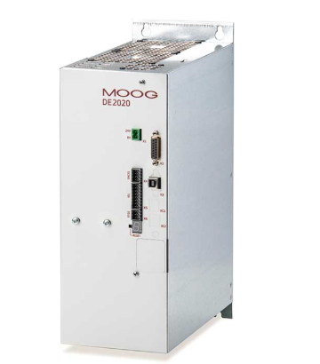 MOOG DE2020 Energy Management System
 -
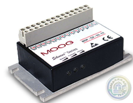 MOOG Silencer® Series Drive Electronics 2-Quadrant Speed Controllers for Brushless Motors
 -
 MOOG MSD Modular Multi-Axis Servo Drive System
 -
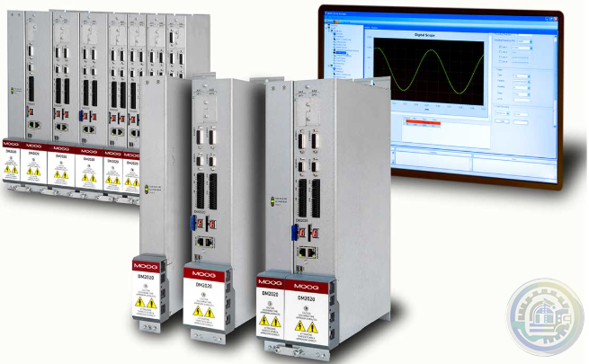 MOOG DM2020 Digital Multi-Axis Servo Drive
 -
 MOOG DM2020 Drive System Overview
 -
 MOOG DS2020 Digital Single-Axis Servo Drive
 -
 MOOG Reconfigurable Actuation Control Unit Family
 -
 MOOG 2-channel Electronic Control Unit (ECU)
 -
 Bachmann CMS – Modules, Measuring Systems and Sensors
 -
 Bachmann CMS – Condition Monitoring System
 -
 Bachmann M-JVIS, M-JSYS Java Libraries
 -
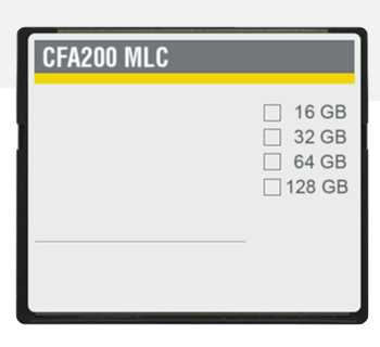 Bachmann CFA200 MLC CFast Memory for HMI devices only
 -
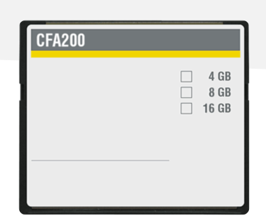 Bachmann CFA200 SLC CFast Memory Memory card
 -
 Bachmann Operator Terminal Systemsoftware
 -
 Bachmann Operator Terminal System Software
 -
 Bachmann Die Operator Terminals der OT1300-Produktserie vereinen
 -
 Bachmann Das Web Terminal OT1200
 -
 Bachmann OT1200 Web Terminal Panel PC Series
 -
 Bachmann OT1300 Operator Terminal Panel PC Series
 -
 Bachmann PPC1200 ECO series panel PCs
 -
 Bachmann Panel PCs The optimum operator terminal for every application
 -
 Prosoft PLX31-EIP-MBS EtherNet/IP™ to Modbus® Serial Communication Gateway
 -
 Prosoft PLX31-EIP-MBS4 EtherNet/IP to Modbus Serial 4 Port
 -
 Prosoft PLX31-EIP-MBTCP EtherNet/IP™ to Modbus® TCP/IP Communication Gateway
 -
 Prosoft AN-X-TI EtherNet/IP to Texas Instruments Remote I/O Master Gateway, non-CE
 -
 Moog Gimbal Control Electronics (GCE)
 -
 Moog Downhole Motor Controllers
 -
 Moog Main CPU 6031 CPU MODULES
 -
 Moog Machine Controller (MC Series 600)
 -
 MOOG Machine Controllers Series 600 (MC600)
 -
 MOOG MC600 Series Machine Controller
 -
 Prosoft MVI69-DFNT EtherNet/IP Client/Server Communication Module for CompactLogix
 -
 Prosoft MVI69-EGD GE Ethernet Global Data Communication Module
 -
 Prosoft MVI69-S3964R Siemens 3964R Protocol Communication Module
 -
 Prosoft MVI69-FLN FA Control Network Communication Module
 -
 Prosoft MVI69L-MBS Modbus Serial Lite Communication Module
 -
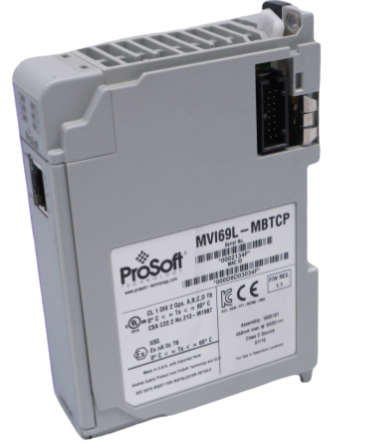 Prosoft MVI69L-MBTCP Modbus TCP/IP Lite Communication Module
 -
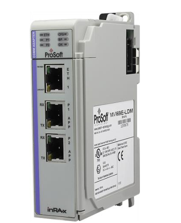 Prosoft MVI69E-LDM Linux Development Module for CompactLogix™
 -
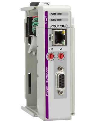 Prosoft ILX69-PBS PROFIBUS DPV1 Slave for CompactLogix
 -
 Prosoft ILX69-PBM PROFIBUS DPV1 Master for CompactLogix
 -
 Prosoft MVI69E-AFC Enhanced Liquid & Gas Flow Computer for CompactLogix®
 -
 Prosoft MVI69E-GEC Generic ASCII Ethernet Communication Module
 -
 Prosoft MVI69E-GSC Generic ASCII Serial Communication Module
 -
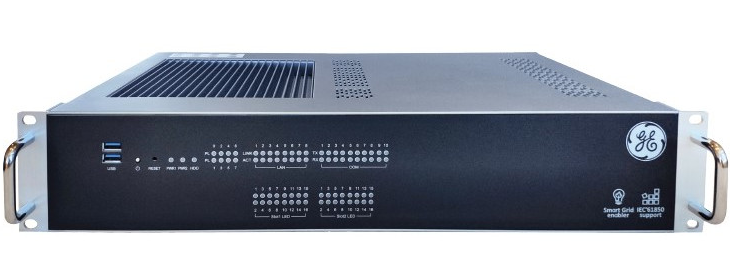
 Prosoft PLX82-EIP-61850 EtherNet/IP™ Server to IEC 61850 Client Gateway
 -
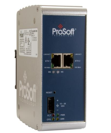
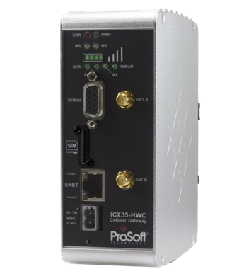 Prosoft ICX35-HWC Industrial Cellular Gateway
 -
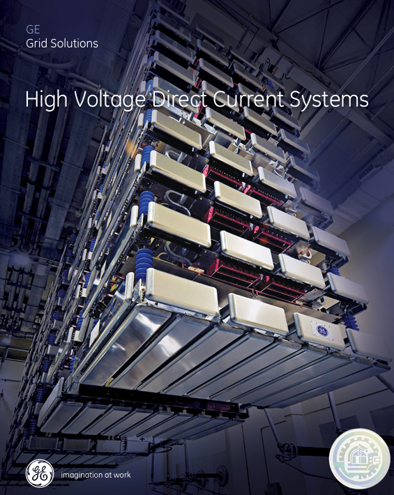 GE High Voltage Direct Current Systems
 -
 GE Vernova’s GridNode DER Management
 -
 GE GridNode Microgrid Controller
 -
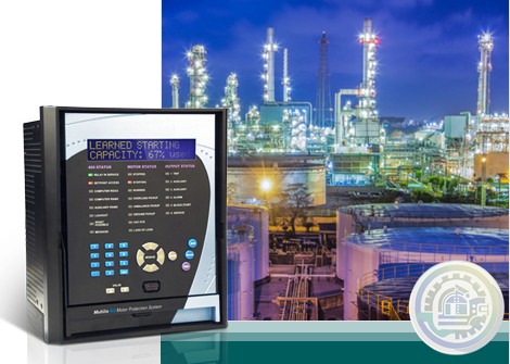 GE Multilin 469 Motor Protection System
 -
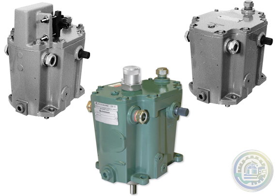 Woodward TG-13 and TG-17 Governors TG611-13 and TG611-17 Governors
 -
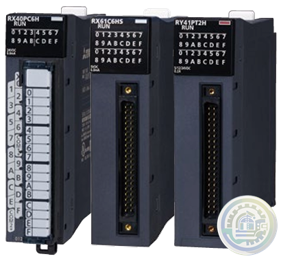 MITSUBISHI ELECTRIC MELSEC iQ-R Series
 -
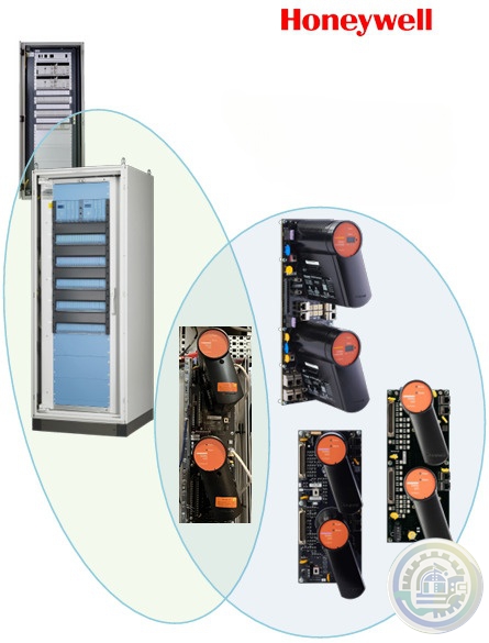 Honeywell Safety Management Systems R210.6
 -
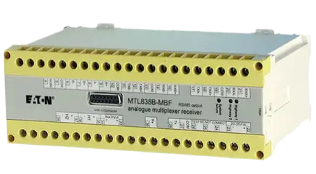 Eaton MTL838B-MBF Analogue Multiplexer Receiver
 -
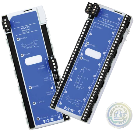 Eaton MTL838C-MBF MTL fieldbus networks
 -
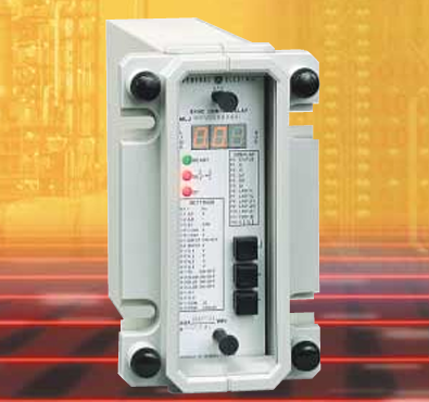 GE MLJ Digital Synchromism Check
 -
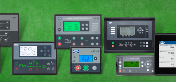
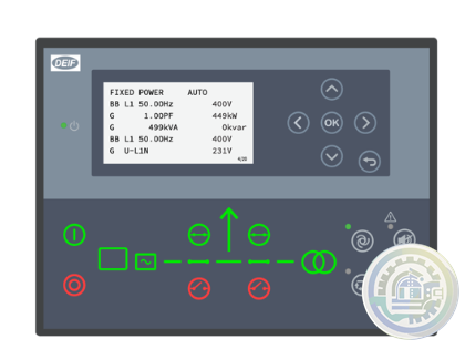 DEIF AGC 150 Generator Advanced Genset Controller
 -
 DEIF ATS controllers – Reliable, flexible & efficient power transfer solutions
 -
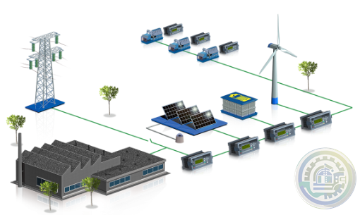 DEIF Hybrid microgrid controllers
 -
 DEIF Digital voltage controllers
 -
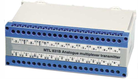 Eaton MTL831B IS analogue multiplexer transmitter
 -
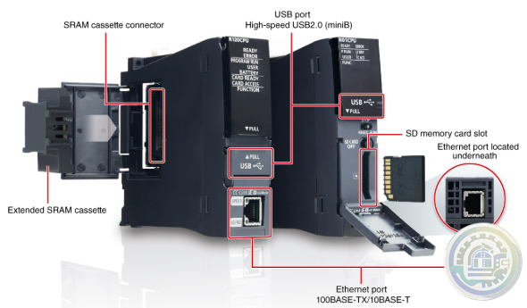 Mitsubishi Controllers MELSEC iQ-R Series
 -
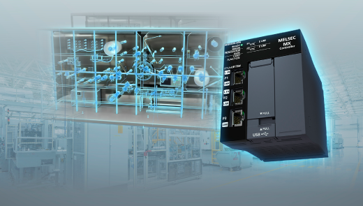 Mitsubishi MELSEC MX Controller MX-F model
 -
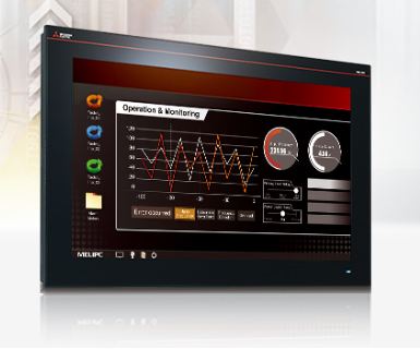 Mitsubishi Industrial Computer MELIPC Series MI3321G-W/MI3315G-W Product features
 -
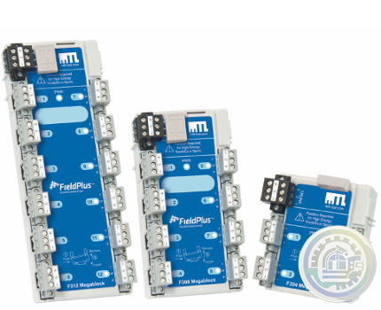
 Eaton F300 megablock range MTL fieldbus device couplers
 -
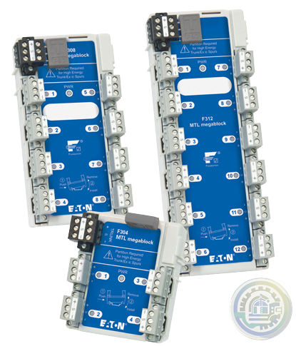
 Eaton F200-IS megablock range MTL intrinsically safe fieldbus device couplers
 -
Eaton MTL F300 megablock range
-
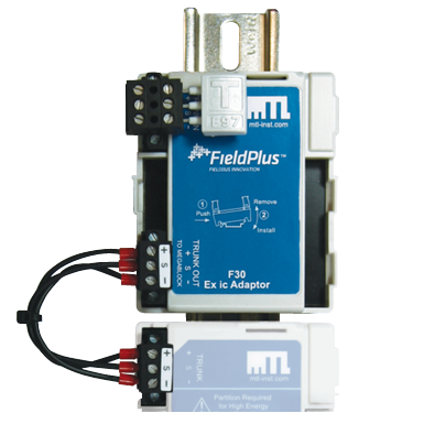 Eaton F30 Ex ic Adaptor F300 Fieldbus Device Couplers Accessory
 -
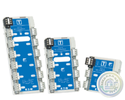 Eaton MTL Megablock range of wiring hubs
Please do not listen to the advice of non-professional engineers! Cause equipment damage!


wechat/whatsapp:
+86-181-44100-983
Email: kongjiangauto@163.com
-
Woodward 8440-1706 Synchronizer Module | SPM-D11 Generator Control
-
WOODWARD 8440-2052 H Digital speed controller
-
Woodward PEAK200-HVAC 8200-1501 digital steam turbine controller
-
Woodward EASYGEN-3200-5 8440-1992 A Genset Control
-
Woodward 8440-2052 EasyGen 3200-5-P2 Genset Controller
Copyright © 2009 - 2024 Cld , All Rights Reserved K-JIANG All rights reserved