-
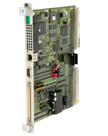
GE Mark VIe & VIeS IS230PCAAH1B - Core Analog I/O Module
-
GE Mark VIe & VIeS IS230PCAAH1A Core Analog I/O Module
-
Emerson PMCSPANA/IH PMC Carrier Installation and Use Manual
-
Emerson PMCSPAN26E-010 Secondary PMC expansion
-
Emerson PMCSPAN26E-002 Primary PMC expansion
-
Emerson Контроллер расхода панельного монтажа FloBoss™ S600+ Remote Automation Solutions
-
Emerson Контроллер расхода панельного монтажа FloBoss™ S600+
-
Emerson Maersk Oil Chooses Emerson’s FloBoss™ S600+ for their Offshore Oil & Gas Fiscal Metering System
-
Emerson Config600™ Configuration Software
-
Emerson Upgrading from the Original FloBoss S600 to the New FloBoss S600+
-
Emerson FloBoss™ S600+ Frequently Asked Questions Interfaces
-
Emerson FloBoss™ S600+ Frequently Asked Questions Configuration
-
Emerson FloBoss™ S600+ Frequently Asked Questions Hardware 2
-
Emerson FloBoss™ S600+ Frequently Asked Questions Hardware
-
Emerson FloBoss™ S600 Flow Manager Specification Sheet Functions
-
Emerson FloBoss™ S600 Flow Manager Specification Sheet
-
Emerson DeltaV™ Smart Switches Product Specifications
-
Emerson DeltaV™ Smart System Compatibility
-
Emerson DeltaV™ Smart Switches Packet rate limiting
-
Emerson DeltaV™ Smart Switches Auto Security Lockdown
-
Emerson DeltaV™ Smart Switches Smart Switch Commissioning
-
Emerson DeltaV™ Smart Switches Benefits DeltaV Network Device Command Center
-
Emerson DeltaV Distributed Control System DeltaV™ Smart Switches Benefits
-
Emerson DeltaV Distributed Control System DeltaV™ Smart Switches
-
ABB Cyberex® SuperSwitch®GT Standards conformance
-
ABB Cyberex® SuperSwitch®GT Technical specifications
-
ABB Cyberex® SuperSwitch®GT
-
ABB Cyberex® Cyberwave DC Charger Standard features
-
ABB Cyberex® Cyberwave DC Charger
-
ABB Cyberex Mission Critical (MC) Series Highlights
-
ABB Cyberex® Power Distribution Unit (PDU) Power distribution system
-
ABB Cyberex® Mission Critical (MC) 200–800A digital static transfer switch and PDU integration
-
ABB SuperSwitch®4 technology Expert power management
-
ABB SuperSwitch®4 technology Best solution: A real time switching method
-
ABB Dynamic inrush restraint for applications with downstream transformers
-
ABB SuperSwitch®4 technology key applications
-
ABB SuperSwitch®4 technology 200A–4000A (3-pole) 200A–800A (4-pole)
-
Emerson DeltaV™ Smart Switches Benefits Accessing the Console
-
Emerson DeltaV™ Smart Switches Benefits Improved performance
-
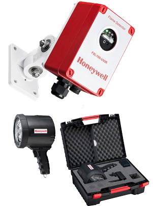
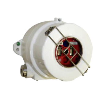
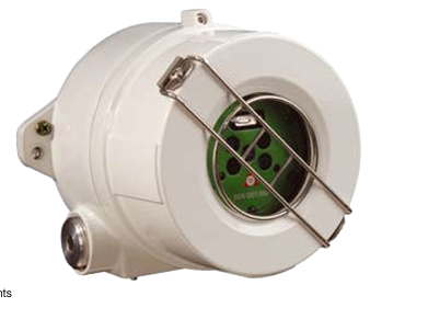
Honeywell Fixed Flame Detectors FSL100 Flame Detectors Features & Benefits
-
Honeywell Fixed Flame Detectors FSL100 Flame Detectors
-
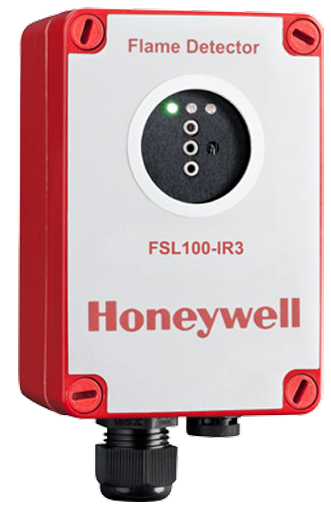
Honeywell FSL100 Series FSL100-IR3 Flame Detectors
-
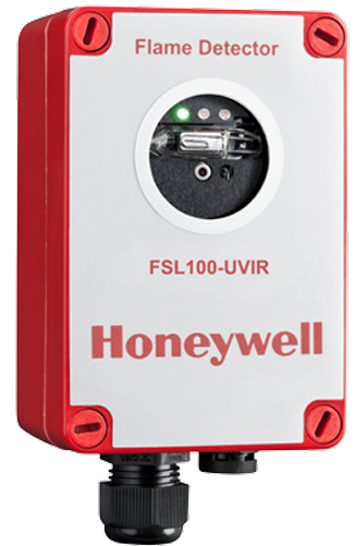
Honeywell FSL100 Series FSL100-UV/IR Flame Detectors
-
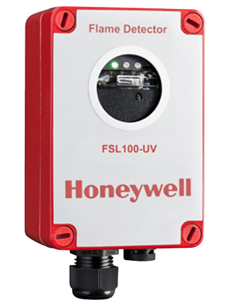
Honeywell FSL100 Series FSL100-UV Flame Detectors
-
Honeywell FSL100 Series Flame Detectors
-
Honeywell Fire Sentry FS20X FireAnalytics Lines of Business
-
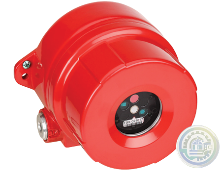
Honeywell Fire Sentry FS20X Fire and Flame Detector Conventional
-
Honeywell Fire Sentry FS20X Fire and Flame Detector Benefits
-
Honeywell Fire Sentry FS20X Fire and Flame Detector
-
Honeywell FS20X Fire and Flame Detector
-
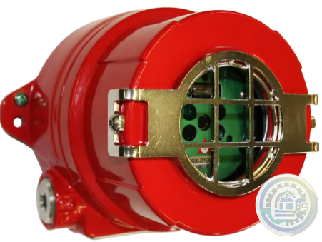
Honeywell FS24X Detector FEATURES True triple IR wide band sensing and sophisticated detection algorithms
-
Honeywell FS24X Detector True triple IR wide band sensing and sophisticated detection algorithms
-
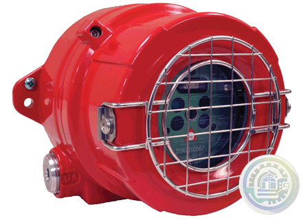
Honeywell FS20X Advanced Multi Spectrum (UV/Dual IR/VIS) Flame Detector FEATURES
-
Honeywell FS20X Advanced Multi Spectrum (UV/Dual IR/VIS) Flame Detector
-
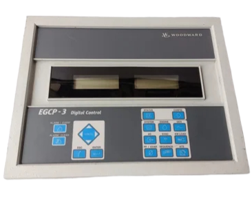
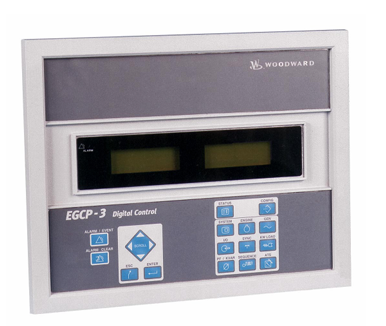
Woodward EGCP-3 Generator System Control Package HARDWARE SPECIFICATIONS
-
Woodward EGCP-3 Generator System Control Package Functions
-
Woodward EGCP-3 Generator System Control Package APPLICATIONS
-
Woodward EGCP‐3 LS and SPM‐D on the Yacht Sea Jewel Application
-
Woodward EGCP‐3 LS and SPM‐D on the Yacht Sea Jewel
-
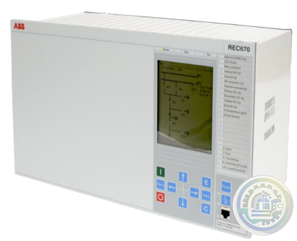
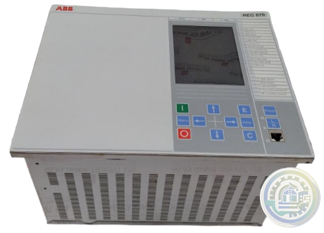
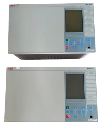
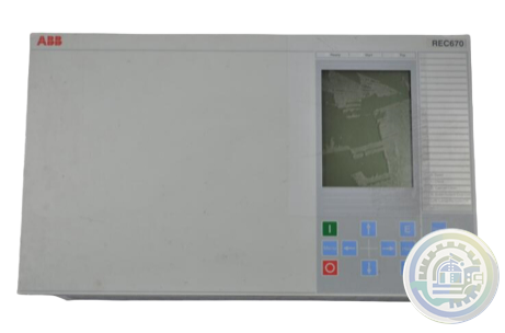
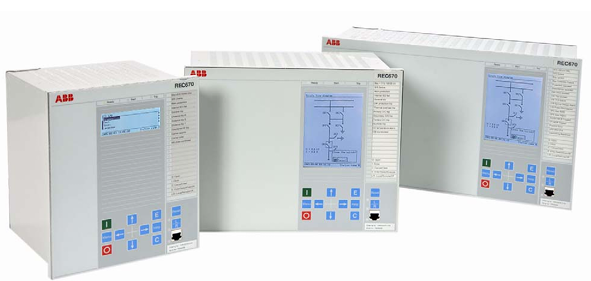
ABB REC 670 Bay control IED Functionality
-
ABB REC 670 Bay control IED Application
-
ABB REC 670 Bay control IED Functions 2
-
ABB REC 670 Bay control IED Functions
-
ABB REC 670 Bay control IED Features
-
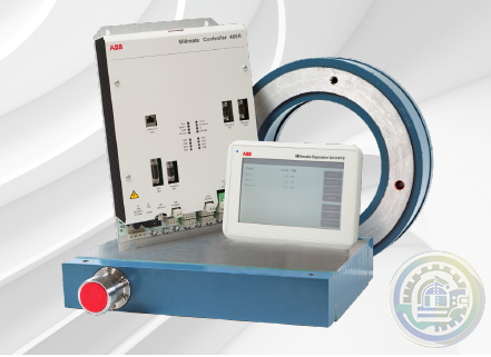
ABB Millmate Roll Force System Health check Service duration
-
ABB Millmate Roll Force System Health check Overview
-
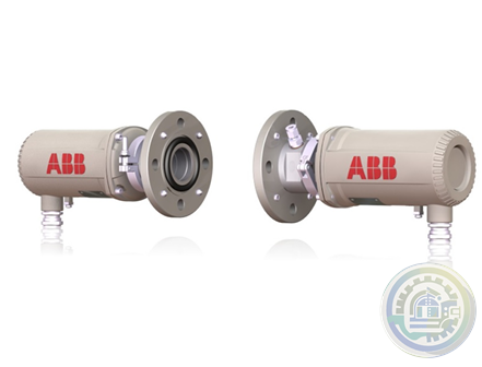
ABB LS4000 Tunable diode laser analyzer Certifications
-
ABB LS4000 Tunable diode laser analyzer Technical data
-
ABB LS4000 Tunable diode laser analyzer Introduction
-
ABB LS4000 How it works – measuring principle
-
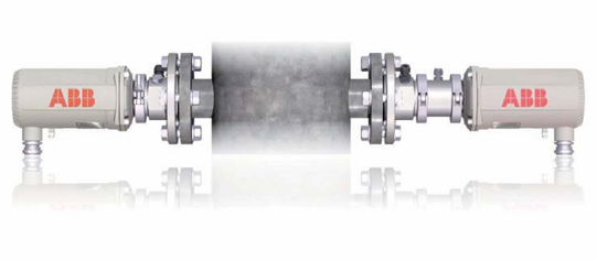
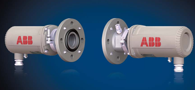
ABB LS4000 Tunable diode laser analyzer
-
ABB KB² Fibre-Optic Sheet Break Detector Benefits
-
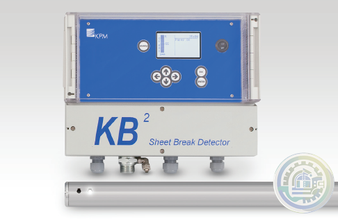
ABB KB² Fibre-Optic Sheet Break Detector
-
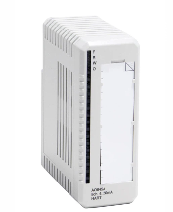
AO845A ABB Ability™ System 800xA® hardware selector
-
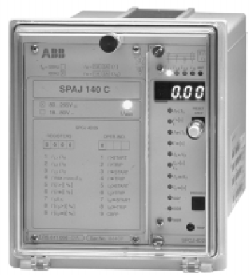
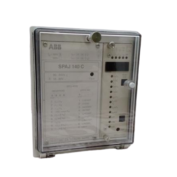
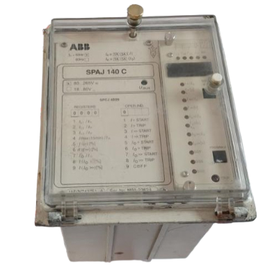
ABB SPAJ 140 C Combined overcurrent andearth-fault relay Features
-
ABB SPAJ 140 C Series A world-class relay collection for optimised protection functions
-
ABB SPAJ 140 C Series Combined Overcurrent and Earth-fault Relays
-
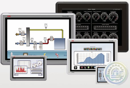
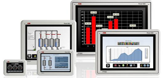
ABB PANEL 800 VERSION 6.2
-
ABB Compact Product Suite Panel 800 Version 6
-
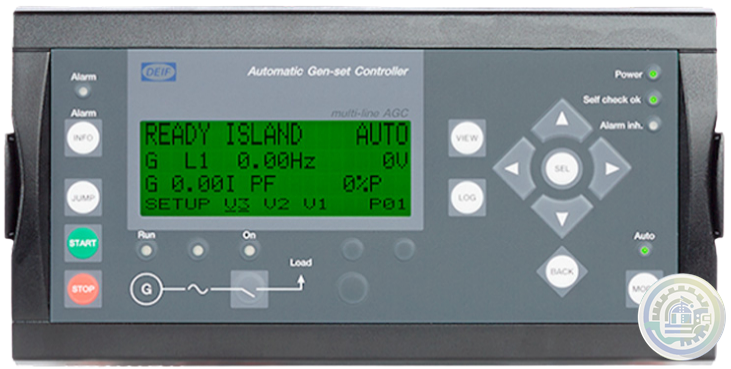
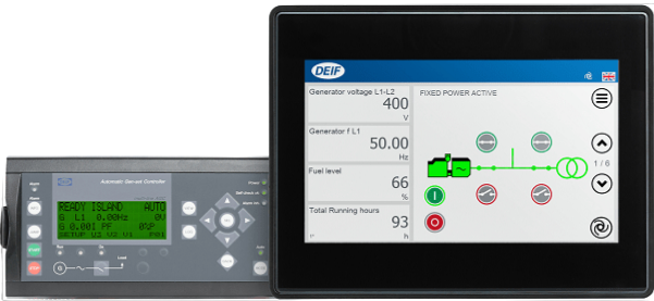
DEIF Automatic Genset Controller AGC-4 features
-
DEIF Automatic Genset Controller AGC-4
-
Emerson KJ4002X1-BE1 Top Extender Cable Assembly
-
Emerson PMCspan PMC Expansion Mezzanine Specifications
-
Emerson PMCspan PMC Expansion Mezzanine Details
-
Emerson PMCspan PMC Expansion Mezzanine
-
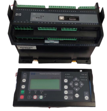
DEIF DU-2/MKIII Paralleling And Protection Unit 24VDC Applications
-
DEIF DU-2/MKIII Paralleling And Protection Unit 24VDC
-
Alstom/General Electric controller with SPU232.2 029.366.817
-
Alstom/General Electric controller with ICP232 029.359325
-
ABB excitation board card 3BHE014967R0002 UNS 2880B-P,V2
-
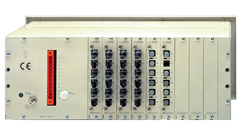
ABB Lon Star-Coupler RER 111
-
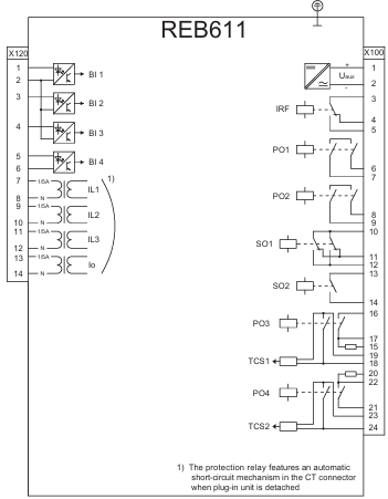
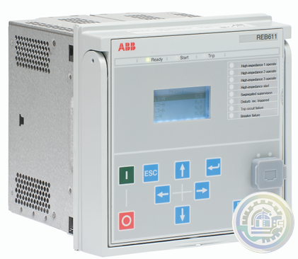
ABB REB611 Busbar and Multipurpose Differential Protection Tools
-
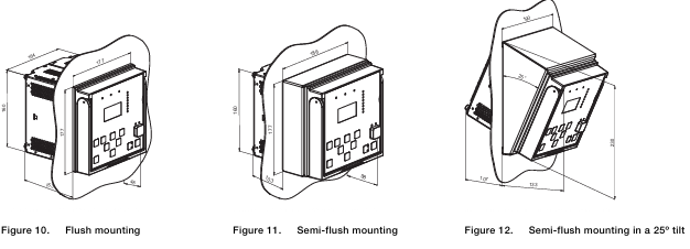
ABB REB611 Busbar and Multipurpose Differential Protection Mounting methods
-
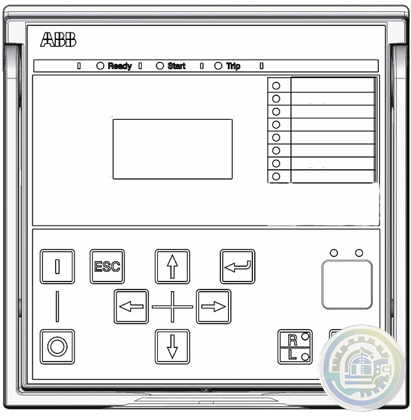
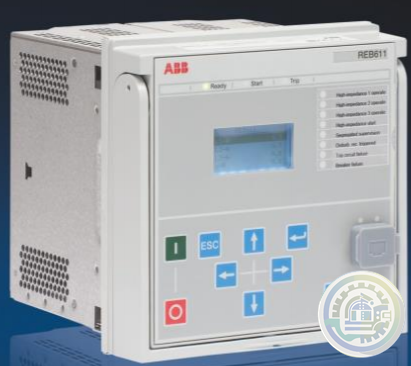
ABB REB611 Busbar and Multipurpose Differential Protection Local HMI
-
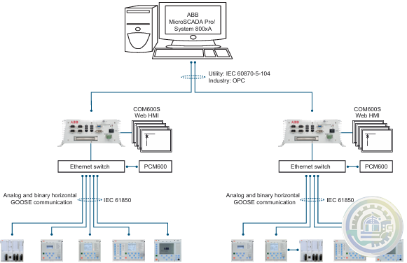
ABB REB611 Busbar and Multipurpose Differential Protection Station communication 2
-
ABB REB611 Busbar and Multipurpose Differential Protection Station communication
-
ABB REB611 Busbar and Multipurpose Differential Protection Access control
-
ABB REB611 Busbar and Multipurpose Differential Protection Recorded data
-
ABB REB611 Busbar and Multipurpose Differential Protection Control
-
ABB REB611 Busbar and Multipurpose Differential Protection Supported ABB solutions
-
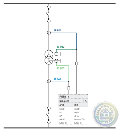
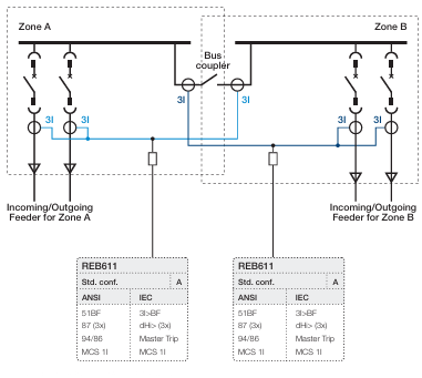
ABB REB611 Busbar and Multipurpose Differential Protection Application
-
ABB REB611 Busbar and Multipurpose Differential Protection functions
-
ABB REB611 Busbar and Multipurpose Differential Protection and Control
-
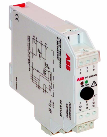
ABB PF 900-NR Power Feed Module
-
ABB HS 810 Head station for LD 800P
- Bristol Babcock
- Rolls-Royce
- Aerotech
- APPLIED MATERIALS
- Basler
- SAACKE
- BENDER
- Kollmorgen
- MEGGITT
- METSO
- MITSUBISHI
- MTL
- HIMA
- Siemens
- BACHMANN
- AMAT
- DEIF
- DELTATAU
- EATON
- ELAU
- LAM
- SCHNEIDER
- Advantest
- ABB
- GE
- Emerson
- Motorola
- A-B
- KUKA
- Abaco
- HITACHI
- SST
- Vibro-Meter
- Rexroth
- Prosoft
- DFI
- Scanlab
- Reliance
- Parker
- Woodward
- MOOG
- NI
- FOXBORO
- Triconex
- Bently
- ALSTOM
- YOKOGAWA
- B&R
- UNIOP
- KONGSBERG
- Honeywell
- Omron
- CTI
- EPRO
- Tell:+86-18144100983
- email:kongjiangauto@163.com
- Application:wind/ petroleum/ chemical/ natural gas/ Marine/ mining/ aviation/ electronics/ steel/ nuclear power/ electric power/ coking/ air separation and so on
- Series:PLC/ DCS/ servo/ analog/ Ethernet/ digital/ redundant module/ tension system/ excitation/ generator management/ human-machine interface/ detection card/ sensor/ AC drive/ etc

Power requirements depend on the number and type of modules supplied for each system. For a system
with a single I/O chassis, size the input power source according to the rating of the MicroNet Plus power
supply to which the source is connected. Do not size the supply mains for the sum of the MicroNet Plus
power supply ratings when redundant supplies are used. MicroNet Plus supplies are redundant when
installed in the same chassis. Redundant supplies share the load between them equally, but each must
provide for full load in the event that one of the units is disabled.
Table 4-3 gives the maximum overload
protection for supply mains connected to any single or redundant pair of MicroNet Plus main power
supplies. It is not recommended that both MicroNet Plus main power supplies of a redundant pair be
connected to a single source, since failure of that source would disable the system.
Multiple chassis systems using MicroNet Plus power supplies may have power supplies of the same
model, but in different chassis, connected to the same source. In this case, each branch to a chassis
must have its own overcurrent protection sized according to Table 4-3. and the power source must be
sized for the sum of the branches.

In the event that on supply needs to be replaced, the recommended method for changing
Power Modules is with the power off (to the module being removed and the module being inserted).
The system will tolerate this “cold swap” method without failure.
Each main power supply has four LEDs to indicate power supply health (OK, Input Fault,
Overtemperature, and Power Supply Fault).
See MicroNet Plus Power Supply Troubleshooting (Section 5.5) for a description of the LED indications.
Input power connections are made to the power supply through a plug/header assembly on the front of
the power supply.
| User name | Member Level | Quantity | Specification | Purchase Date |
|---|


Please do not listen to the advice of non-professional engineers! Cause equipment damage!


wechat/whatsapp:
+86-181-4410-0983
Email: kongjiangauto@163.com
-
GE Mark VIe & VIeS IS230PCAAH1B - Core Analog I/O Module
-
GE Mark VIe & VIeS IS230PCAAH1A Core Analog I/O Module
-
ABB UCD224A103 digital input/output module
-
ABB PDD205A0121 power distribution device
-
ABB PDD205A1121 power distribution device
Copyright © 2009 - 2024 Cld , All Rights Reserved K-JIANG All rights reserved


