
-
Mitsubishi Q00JCPU-S8 Universal Programmable Logic Controller (PLC) CPU
-
FX3U-128MT/ESS FX3U128MTESS FX3U-128MT-ESS MITSUBISHI PLC
-
GT1455HS-QTBDE Mitsubishi GT1455HS
-
MODULE OSA104S MITSUBISHI ENCODER ORIGINAL
-
A2NCPU-P21 A2NCPUP21 MITSUBISHI MELSEC
-
ABB SCC-C Sample gas cooler
-
Omron NX1P Machine Automation Controller
-
Omron NX102 Machine Automation Controller
-
Omron NX502 Machine Automation Controller
-
Omron CQM1H Programmable Controller
-
ABB Pluto Safety PLC A compact, powerful and user-friendly safety PLC.
-
AI830A ABB Ability™ System 800xA® hardware selector
-
ABB AO895 3BSC0690087R1 Analog Output IS HART 8 ch
-
ABB AO820 System 800xA hardware selector
-
ABB HBS01-CJC I/O MTUs - SD Series I/O
-
ABB drives for HVAC ACH550 to ACH580 comparison guide
-
ABB AI825 System 800xA hardware selector
-
ABB AO815 System 800xA hardware selector
-
Emerson Fisher™ 377 Trip Valve
-
Prosoft MVI56-104S IEC 60870-5-104 Ethernet Server Communication Module with Edition 2 Support
-
Prosoft MVI56-EGD GE Ethernet Global Data Communication Module
-
Prosoft MVI56-LTQ Limitorque Valve Actuator Master Communication Module
-
Prosoft MVI56E-AFC Enhanced Liquid & Gas Flow Computer for ControlLogix®
-
Prosoft MVI56E-GEC Generic ASCII Ethernet Communication Module
-
Prosoft ILX56-PBM PROFIBUS DPV1 Master/Slave for ControlLogix®
-
Prosoft ILX56-PBS PROFIBUS DPV1 Slave for ControlLogix®
-
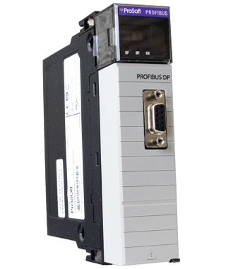
Prosoft PS69-DPS PROFIBUS DP Slave Communication Module
-
Prosoft MVI69E-MBS Modbus Serial Enhanced Communication Module
-
Prosoft ELXM-SW6 ProLinx Edge™ Mini
-
Prosoft RLX2-IHNF-W 802.11abgn Weatherproof IP67 Fast Industrial Hotspot
-
Prosoft WRC-CANX Series CAN bus Extenders
-
Prosoft WRC-CANR-DF Fiber-Optic CAN bus Extenders
-
Prosoft PLX31-MBTCP-MBS Modbus® TCP/IP to Modbus® Serial Communication Gateway
-
Prosoft PLX31-MBTCP-MBS4 Modbus® TCP/IP to Modbus® Serial Four-Port Gateway
-
Prosoft PLX32-EIP-MBTCP EtherNet/IP™ to Modbus® TCP/IP Communication Gateway
-
Prosoft PLX32-EIP-SIE EtherNet/IP™ to Siemens® Industrial Ethernet Communication Gateway
-
Prosoft AN-X2-SQD EtherNet/IP™ to Square D® Remote I/O Gateway
-
Prosoft PLX32-MBTCP-SIE Modbus® TCP/IP to Siemens® Industrial Ethernet Communication Gateway
-
Prosoft PLX31-EIP-PND EtherNet/IP™ to PROFINET® IO Device Gateway
-
ZYGO Coherence Scanning Interferometry (CSI)
-
ZYGO OEM 3D Optical Profiler Systems
-
Prosoft PLX31-PND-MBS PROFINET® Device to Modbus® Serial Gateway
-
Prosoft PLX31-PND-MBS4 PROFINET® Device to Modbus® Serial Gateway with four serial ports
-
Prosoft PLX32-MBTCP-PND Modbus® TCP/IP to PROFINET® Device Gateway
-
Prosoft PLX31-MBTCP-PND Modbus® TCP/IP to PROFINET® Device Gateway
-
Prosoft PLX32-EIP-PND EtherNet/IP™ to PROFINET® Gateway for dual subnets
-
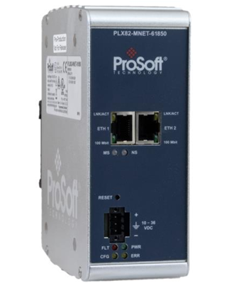
Prosoft PLX82-MNET-61850 Modbus TCP/IP to IEC 61850 Gateway
-
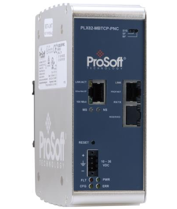
Prosoft PLX82-MBTCP-PNC Modbus® TCP/IP to PROFINET Controller Gateway
-
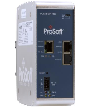
Prosoft PLX82-EIP-PNC EtherNet/IP™ to PROFINET Controller Gateway
-
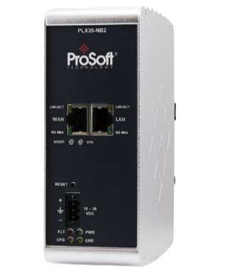
Prosoft PLX35-NB2 Network Bridge
-
Prosoft PLX51-DF1-MSG DF1 Messaging Module
-
Prosoft PLX51-DF1-ENI DF1 Routing Module
-
Prosoft PLX32-EIP-MBTCP-UA EtherNet/IP™ to Modbus® TCP/IP to OPC UA Server Gateway
-
Prosoft PLX51-DL-232 Data Logger
-
Prosoft PLX51-HART-4I 4 Channel HART Input Module
-
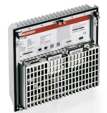
Beckhoff C6525 | Fanless built-in Industrial PC
-
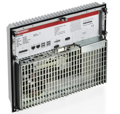
Beckhoff C6515 | Fanless built-in Industrial PC
-
Beckhoff C6043 | Ultra-compact Industrial PC with NVIDIA® GPU
-
Beckhoff C6040 | Ultra-compact Industrial PC
-
Beckhoff C6032 | Ultra-compact Industrial PC
-
Beckhoff C6030 | Ultra-compact Industrial PC
-
Beckhoff C6027 | Fanless ultra-compact Industrial PC
-
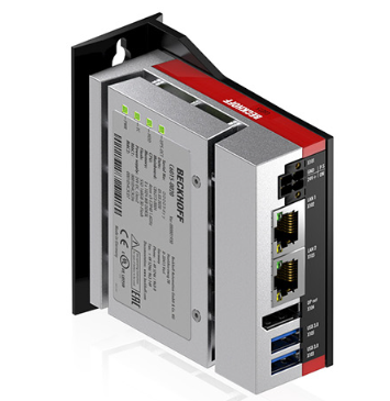
Beckhoff C6025 | Fanless ultra-compact Industrial PC
-
Beckhoff C6017 | Fanless ultra-compact Industrial PC
-
ABB KPM KB2 Sheet Break Detector
-
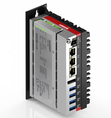
Beckhoff C6015 | Fanless ultra-compact Industrial PC
-
ELAU PacDrive™ Servo drive MC-4
-
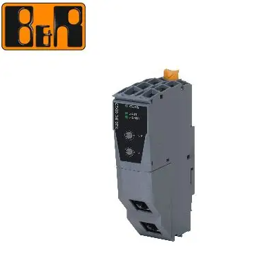
B&R X20CS1012 PLC Module X20 CS 1012
-
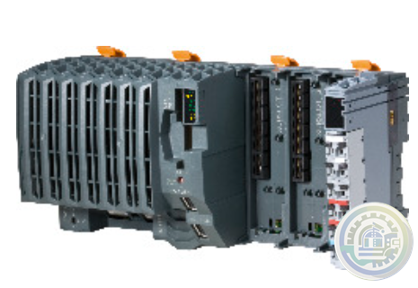
B&R X20BC00G3 X20 Series Controller
-
B&R X20CP0411 1x Ethernet, 2x USB, 1x X2X Link Controller
-
B&R X20CP3585 Controller
-
B&R X20IF10G3-1 Communication module EtherCAT slave
-
B&R X20CM0985 X20 energy measurement and synchronization module
-
Prosoft PLX51-HART-4O 4 Channel HART Output Module
-
Prosoft PLX51-PBS PROFIBUS DP Slave to EtherNet/IP™, Modbus® TCP/IP, or Modbus® Serial Gateway
-
Prosoft PLX51-PBM PROFIBUS DP Master/Slave to EtherNet/IP™, Modbus TCP/IP®, or Modbus® Serial Gateway
-
Prosoft PLX51-DLplus-232 Data Logger Plus
-
Prosoft A-CNR ControlNet Router
-
Prosoft A-TSM/B Time Sync Module
-
Prosoft A-XGPS XPosition Module
-
Prosoft PLX32-EIP-104 EtherNet/IP to IEC 60870-5-104 Gateway
-
Prosoft PLX32-MBTCP-104 Modbus TCP/IP to IEC 60870-5-104 Gateway
-
Prosoft A-PAL/B PA Link Series B PA Gateway
-
Prosoft A-DH485R/B DH485 Router
-
Prosoft PLX51-DNPS Distributed Network Protocol (DNP3) Gateway
-
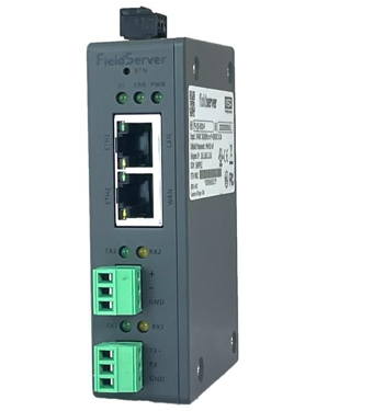
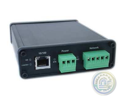
Prosoft PS-QS-2x10-F Universal QuickServer Gateway
-
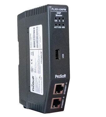
Prosoft PLX51-DNPM Distributed Network Protocol (DNP3) Master Gateway
-
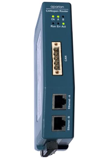
Prosoft A-CANOR/B CANopen Router/B
-
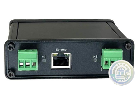
Prosoft PS-QS-3x10-F Universal QuickServer Gateway Dual Ethernet Port
-
Prosoft EtherNet/IP™ to Remote I/O or DH+ Gateway AN-X4-AB-DHRIO
-
Prosoft A-DNTR/B DeviceNet Router Series B
-
Prosoft A-J1939R/B J1939 Router/B
-
Prosoft PS-QS-1x11-F LonWorks QuickServer Gateways
-
Prosoft AN-X3-GENI EtherNet/IP™ to GE Genius™ I/O Gateway
-
Prosoft A-FFL/B FOUNDATION™ Fieldbus H1 Master for EtherNet/IP™ and Modbus® TCP
-
Prosoft ELX3 Industrial Edge Gateway
-
Prosoft A-CFR ControlNet Fiber Repeater
-
Prosoft A-CANBR/B CAN Bus Router/B
-
Prosoft EtherNet/IP™ to Reliance AutoMax DCS or Remote I/O Gateway, non-CE AN-X-AMX
-
Meggitt Flow shutoff valve C327935
-
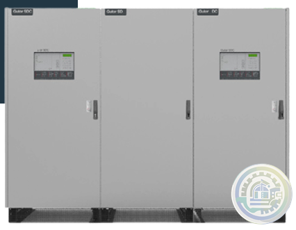
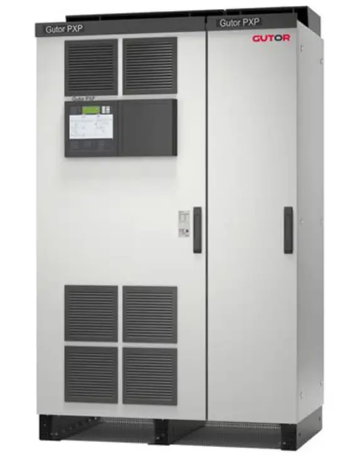
GUTOR PDW AC UPS
-
GUTOR SDC RECTIFIER / BATTERY CHARGER
-
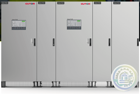
GUTOR WEW / WDW INVERTER SYSTEM
-
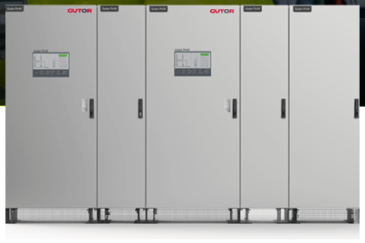
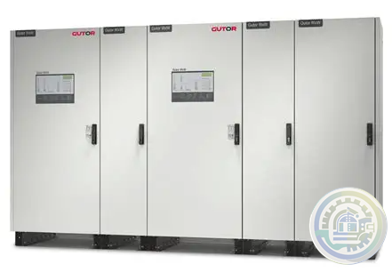
GUTOR MODULAR AC UPS SYSTEM
-
GUTOR SPARE PARTS Minimize downtime of your UPS system
- Beckhoff
- Other brands
- WAGO
- ICS Triplex
- IBA
- Hirschmann
- Bachmann
- Alfa Laval
- Baldor
- Glassman
- Johnson Controls
- Watlow
- ZYGO
- ADVANCED
- KEBA
- Bristol Babcock
- Rolls-Royce
- Aerotech
- Pioneer Magnetics
- Basler
- SAACKE
- BENDER
- Kollmorgen
- MEGGITT
- METSO
- MITSUBISHI
- MTL
- HIMA
- Siemens
- BACHMANN
- AMAT
- DEIF
- DELTATAU
- EATON
- ELAU
- LAM
- SCHNEIDER
- Advantest
- ABB
- GE
- Emerson
- Motorola
- A-B
- KUKA
- Abaco
- HITACHI
- SST
- Vibro-Meter
- Rexroth
- Prosoft
- DFI
- Scanlab
- Reliance
- Parker
- Woodward
- MOOG
- NI
- FOXBORO
- Triconex
- Bently
- ALSTOM
- YOKOGAWA
- B&R
- UNIOP
- KONGSBERG
- Honeywell
- Omron
- CTI
- EPRO


- Tell:+86-18144100983
- email:kongjiangauto@163.com
- Application:wind/ petroleum/ chemical/ natural gas/ Marine/ mining/ aviation/ electronics/ steel/ nuclear power/ electric power/ coking/ air separation and so on
- Series:PLC/ DCS/ servo/ analog/ Ethernet/ digital/ redundant module/ tension system/ excitation/ generator management/ human-machine interface/ detection card/ sensor/ AC drive/ etc
In the event that on supply needs to be replaced, the recommended method for changing
Power Modules is with the power off (to the module being removed and the module being inserted).
The system will tolerate this “cold swap” method without failure.
Each main power supply has four LEDs to indicate power supply health (OK, Input Fault,
Overtemperature, and Power Supply Fault).

See MicroNet Plus Power Supply Troubleshooting (Section 5.5) for a description of the LED indications.
Input power connections are made to the power supply through a plug/header assembly on the front of
the power supply.
For redundant operation, the control can use any combination of power supplies.
The power supplies can only be installed into slots PS1 (power supply #1) and PS2 (power supply #2). If
redundant power supplies are not needed, blanking plates must be installed in the slots not being used.
Branch circuit fuses, circuit breakers, and wiring must meet appropriate codes and authorities having
jurisdiction for the specific country (CE, UL, etc.). See Table 4-3 for maximum recommended fuse or
breaker ratings. Do not connect more than one main power supply to any one fuse or circuit breaker. Use
only the wire sizes specified in Table 4-3. which meet local code requirements. Time delay fuses or circuit
breakers must be used to prevent nuisance trips.
| User name | Member Level | Quantity | Specification | Purchase Date |
|---|


-
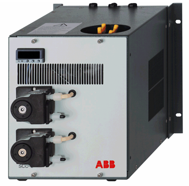 ABB SCC-C Sample gas cooler
 -
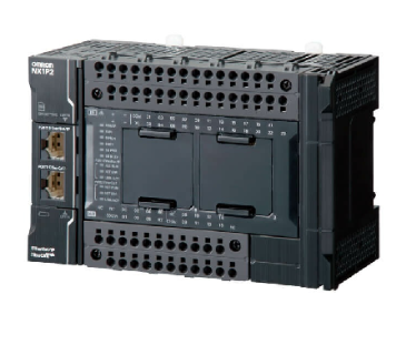 Omron NX1P Machine Automation Controller
 -
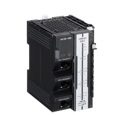 Omron NX102 Machine Automation Controller
 -
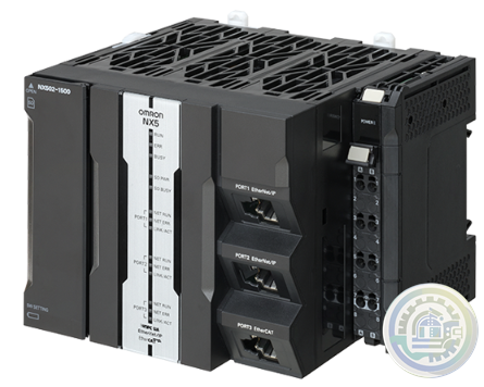 Omron NX502 Machine Automation Controller
 -
 Omron CQM1H Programmable Controller
 -
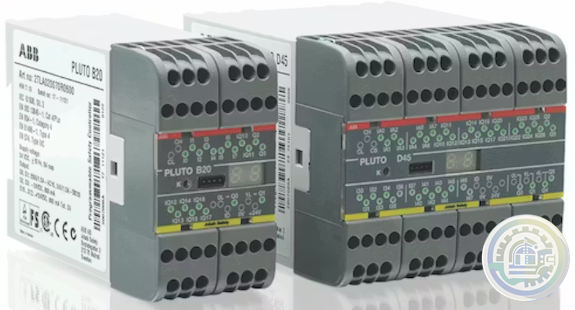 ABB Pluto Safety PLC A compact, powerful and user-friendly safety PLC.
 -
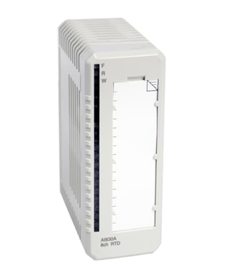 AI830A ABB Ability™ System 800xA® hardware selector
 -
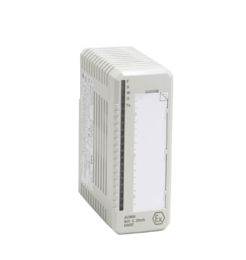 ABB AO895 3BSC0690087R1 Analog Output IS HART 8 ch
 -
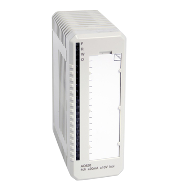 ABB AO820 System 800xA hardware selector
 -
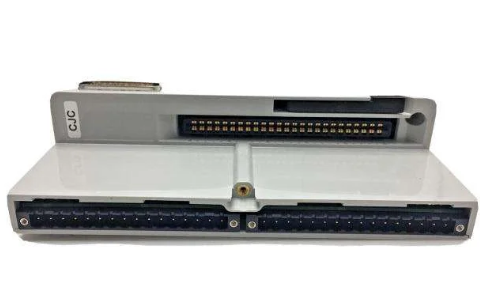 ABB HBS01-CJC I/O MTUs - SD Series I/O
 -
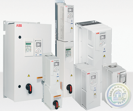 ABB drives for HVAC ACH550 to ACH580 comparison guide
 -
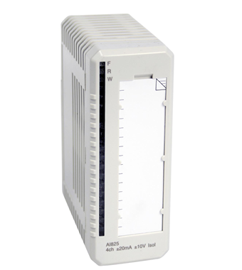 ABB AI825 System 800xA hardware selector
 -
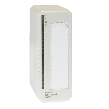 ABB AO815 System 800xA hardware selector
 -
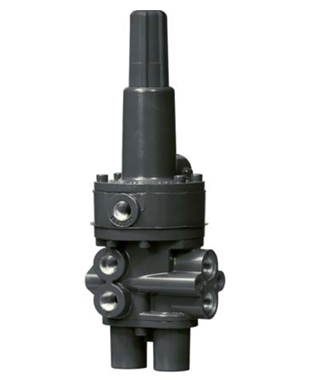 Emerson Fisher™ 377 Trip Valve
 -
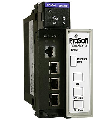 Prosoft MVI56-104S IEC 60870-5-104 Ethernet Server Communication Module with Edition 2 Support
 -
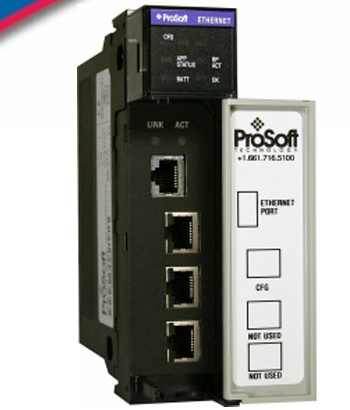 Prosoft MVI56-EGD GE Ethernet Global Data Communication Module
 -
 Prosoft MVI56-LTQ Limitorque Valve Actuator Master Communication Module
 -
 Prosoft MVI56E-AFC Enhanced Liquid & Gas Flow Computer for ControlLogix®
 -
 Prosoft MVI56E-GEC Generic ASCII Ethernet Communication Module
 -
 Prosoft ILX56-PBM PROFIBUS DPV1 Master/Slave for ControlLogix®
 -
 Prosoft ILX56-PBS PROFIBUS DPV1 Slave for ControlLogix®
 -
 Prosoft PS69-DPS PROFIBUS DP Slave Communication Module
 -
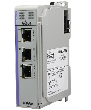 Prosoft MVI69E-MBS Modbus Serial Enhanced Communication Module
 -
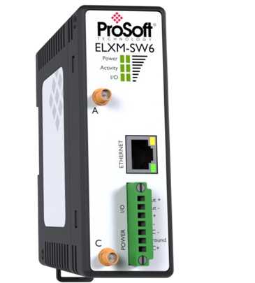 Prosoft ELXM-SW6 ProLinx Edge™ Mini
 -
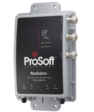 Prosoft RLX2-IHNF-W 802.11abgn Weatherproof IP67 Fast Industrial Hotspot
 -
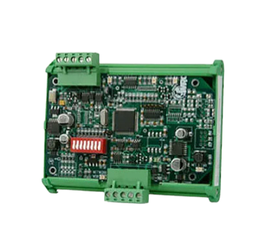 Prosoft WRC-CANX Series CAN bus Extenders
 -
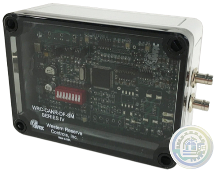 Prosoft WRC-CANR-DF Fiber-Optic CAN bus Extenders
 -
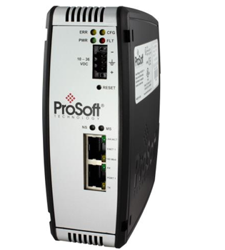 Prosoft PLX31-MBTCP-MBS Modbus® TCP/IP to Modbus® Serial Communication Gateway
 -
 Prosoft PLX31-MBTCP-MBS4 Modbus® TCP/IP to Modbus® Serial Four-Port Gateway
 -
 Prosoft PLX32-EIP-MBTCP EtherNet/IP™ to Modbus® TCP/IP Communication Gateway
 -
 Prosoft PLX32-EIP-SIE EtherNet/IP™ to Siemens® Industrial Ethernet Communication Gateway
 -
 Prosoft AN-X2-SQD EtherNet/IP™ to Square D® Remote I/O Gateway
 -
 Prosoft PLX32-MBTCP-SIE Modbus® TCP/IP to Siemens® Industrial Ethernet Communication Gateway
 -
 Prosoft PLX31-EIP-PND EtherNet/IP™ to PROFINET® IO Device Gateway
 -
 ZYGO Coherence Scanning Interferometry (CSI)
 -
 ZYGO OEM 3D Optical Profiler Systems
 -
 Prosoft PLX31-PND-MBS PROFINET® Device to Modbus® Serial Gateway
 -
 Prosoft PLX31-PND-MBS4 PROFINET® Device to Modbus® Serial Gateway with four serial ports
 -
 Prosoft PLX32-MBTCP-PND Modbus® TCP/IP to PROFINET® Device Gateway
 -
 Prosoft PLX31-MBTCP-PND Modbus® TCP/IP to PROFINET® Device Gateway
 -
Prosoft PLX32-EIP-PND EtherNet/IP™ to PROFINET® Gateway for dual subnets
-
 Prosoft PLX82-MNET-61850 Modbus TCP/IP to IEC 61850 Gateway
 -
 Prosoft PLX82-MBTCP-PNC Modbus® TCP/IP to PROFINET Controller Gateway
 -
 Prosoft PLX82-EIP-PNC EtherNet/IP™ to PROFINET Controller Gateway
 -
 Prosoft PLX35-NB2 Network Bridge
 -
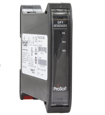 Prosoft PLX51-DF1-MSG DF1 Messaging Module
 -
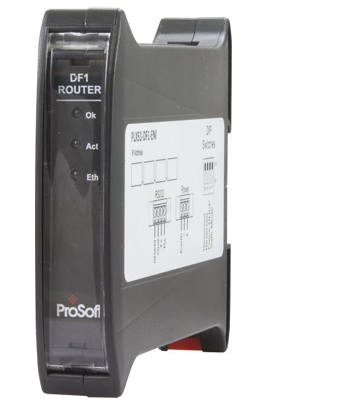 Prosoft PLX51-DF1-ENI DF1 Routing Module
 -
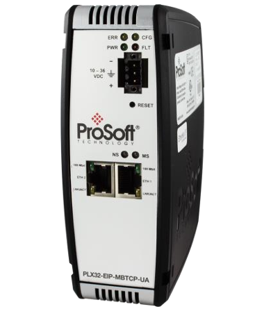 Prosoft PLX32-EIP-MBTCP-UA EtherNet/IP™ to Modbus® TCP/IP to OPC UA Server Gateway
 -
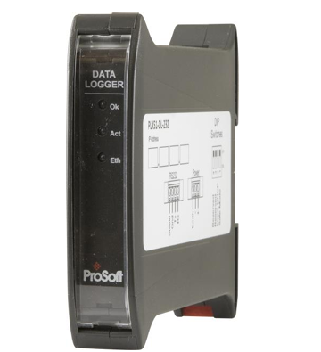 Prosoft PLX51-DL-232 Data Logger
 -
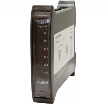 Prosoft PLX51-HART-4I 4 Channel HART Input Module
 -
 Beckhoff C6525 | Fanless built-in Industrial PC
 -
 Beckhoff C6515 | Fanless built-in Industrial PC
 -
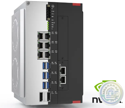 Beckhoff C6043 | Ultra-compact Industrial PC with NVIDIA® GPU
 -
 Beckhoff C6040 | Ultra-compact Industrial PC
 -
 Beckhoff C6032 | Ultra-compact Industrial PC
 -
 Beckhoff C6030 | Ultra-compact Industrial PC
 -
 Beckhoff C6027 | Fanless ultra-compact Industrial PC
 -
 Beckhoff C6025 | Fanless ultra-compact Industrial PC
 -
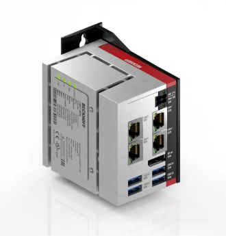 Beckhoff C6017 | Fanless ultra-compact Industrial PC
 -
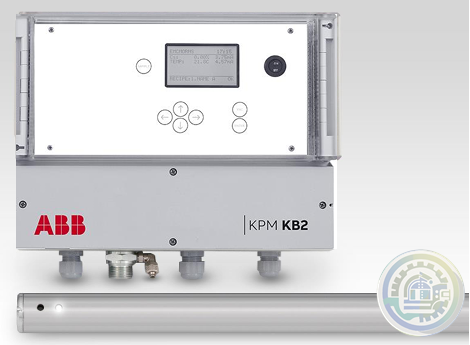 ABB KPM KB2 Sheet Break Detector
 -
 Beckhoff C6015 | Fanless ultra-compact Industrial PC
 -
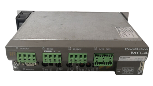 ELAU PacDrive™ Servo drive MC-4
 -
 B&R X20CS1012 PLC Module X20 CS 1012
 -
 B&R X20BC00G3 X20 Series Controller
 -
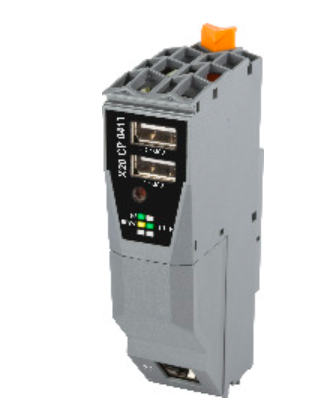 B&R X20CP0411 1x Ethernet, 2x USB, 1x X2X Link Controller
 -
 B&R X20CP3585 Controller
 -
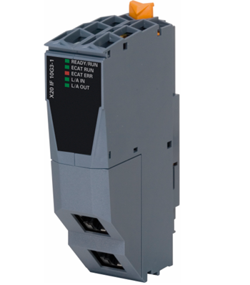 B&R X20IF10G3-1 Communication module EtherCAT slave
 -
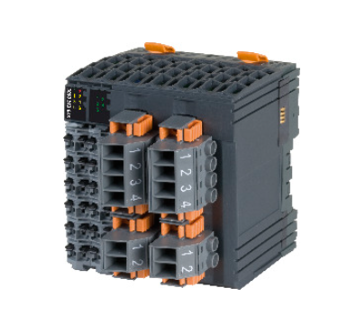 B&R X20CM0985 X20 energy measurement and synchronization module
 -
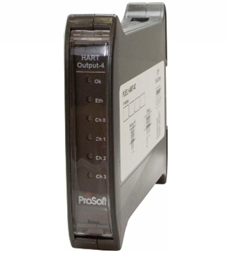 Prosoft PLX51-HART-4O 4 Channel HART Output Module
 -
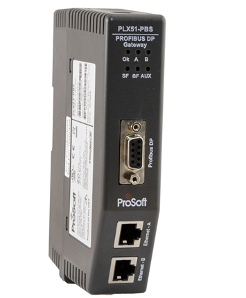 Prosoft PLX51-PBS PROFIBUS DP Slave to EtherNet/IP™, Modbus® TCP/IP, or Modbus® Serial Gateway
 -
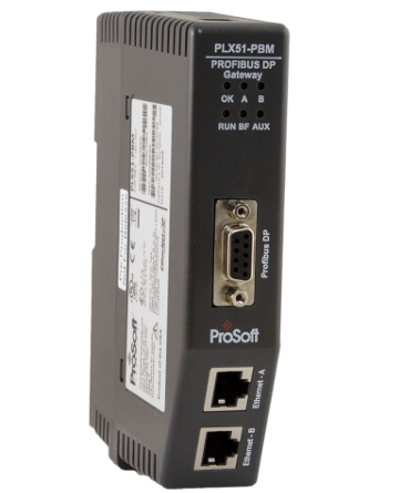 Prosoft PLX51-PBM PROFIBUS DP Master/Slave to EtherNet/IP™, Modbus TCP/IP®, or Modbus® Serial Gateway
 -
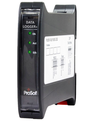 Prosoft PLX51-DLplus-232 Data Logger Plus
 -
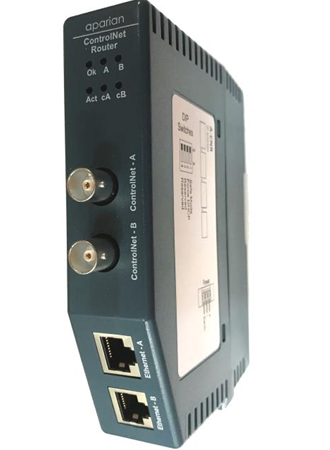 Prosoft A-CNR ControlNet Router
 -
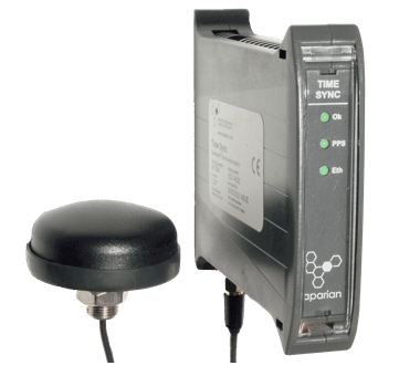 Prosoft A-TSM/B Time Sync Module
 -
 Prosoft A-XGPS XPosition Module
 -
 Prosoft PLX32-EIP-104 EtherNet/IP to IEC 60870-5-104 Gateway
 -
 Prosoft PLX32-MBTCP-104 Modbus TCP/IP to IEC 60870-5-104 Gateway
 -
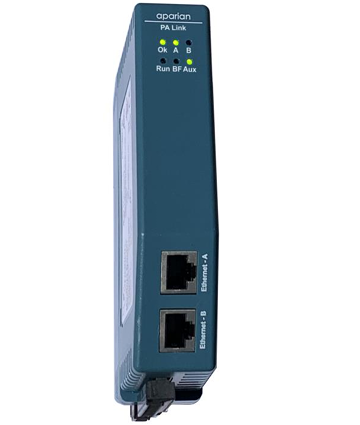 Prosoft A-PAL/B PA Link Series B PA Gateway
 -
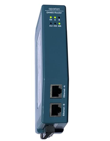 Prosoft A-DH485R/B DH485 Router
 -
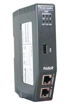 Prosoft PLX51-DNPS Distributed Network Protocol (DNP3) Gateway
 -
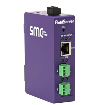 Prosoft PS-QS-2x10-F Universal QuickServer Gateway
 -
 Prosoft PLX51-DNPM Distributed Network Protocol (DNP3) Master Gateway
 -
 Prosoft A-CANOR/B CANopen Router/B
 -
 Prosoft PS-QS-3x10-F Universal QuickServer Gateway Dual Ethernet Port
 -
 Prosoft EtherNet/IP™ to Remote I/O or DH+ Gateway AN-X4-AB-DHRIO
 -
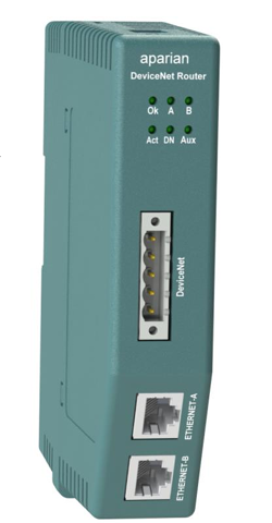 Prosoft A-DNTR/B DeviceNet Router Series B
 -
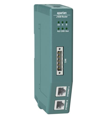 Prosoft A-J1939R/B J1939 Router/B
 -
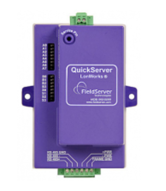 Prosoft PS-QS-1x11-F LonWorks QuickServer Gateways
 -
 Prosoft AN-X3-GENI EtherNet/IP™ to GE Genius™ I/O Gateway
 -
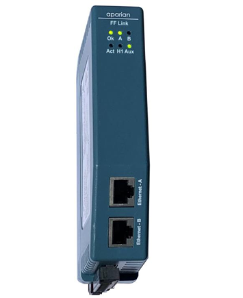 Prosoft A-FFL/B FOUNDATION™ Fieldbus H1 Master for EtherNet/IP™ and Modbus® TCP
 -
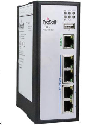 Prosoft ELX3 Industrial Edge Gateway
 -
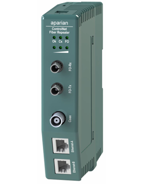 Prosoft A-CFR ControlNet Fiber Repeater
 -
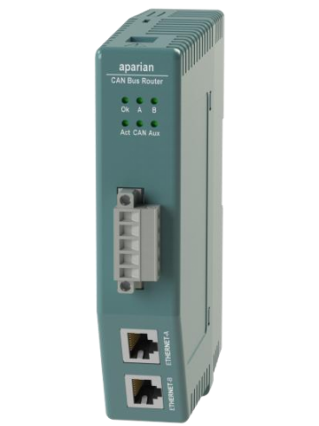 Prosoft A-CANBR/B CAN Bus Router/B
 -
 Prosoft EtherNet/IP™ to Reliance AutoMax DCS or Remote I/O Gateway, non-CE AN-X-AMX
 -
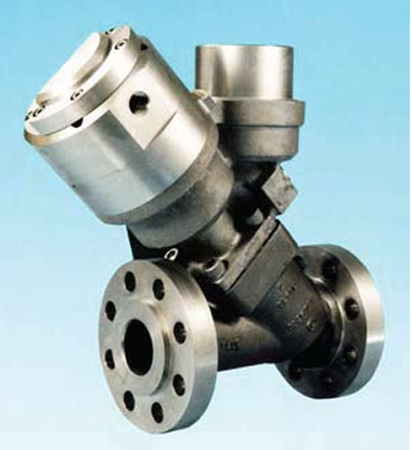 Meggitt Flow shutoff valve C327935
 -
 GUTOR PDW AC UPS
 -
 GUTOR SDC RECTIFIER / BATTERY CHARGER
 -
 GUTOR WEW / WDW INVERTER SYSTEM
 -
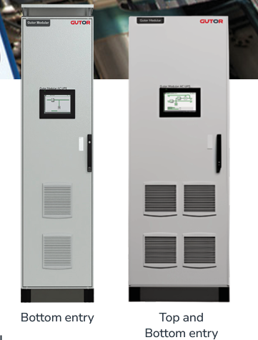 GUTOR MODULAR AC UPS SYSTEM
 -
 GUTOR SPARE PARTS Minimize downtime of your UPS system
 -
 GUTOR PDW AC UPS
 -
 GE MVAJM High Speed Tripping and Control Relays
 -
 GE MVAJ 31 Tripping and Control Relays
 -
 GE MVAJ 11 to 34 Tripping and Control Relays
 -
 GE MVAJ 05/10/20 Tripping and Control Relays
 -
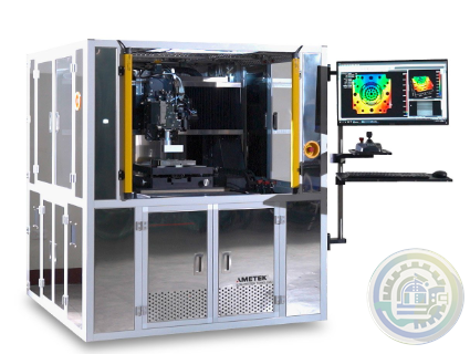
 ZYGO Guardian™ Industrial Enclosure
 -
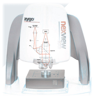
 ZYGO Nexview™ 650: Large Format Inspection & Metrology
 -
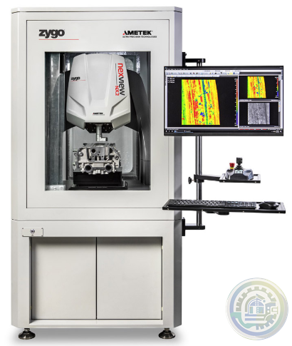
 ZYGO NewView™ 9000 with Coherence Scanning Interferometry Technology
 -
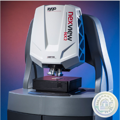 ZYGO Nexview™ NX2 3D Optical Profiler
 -
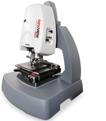
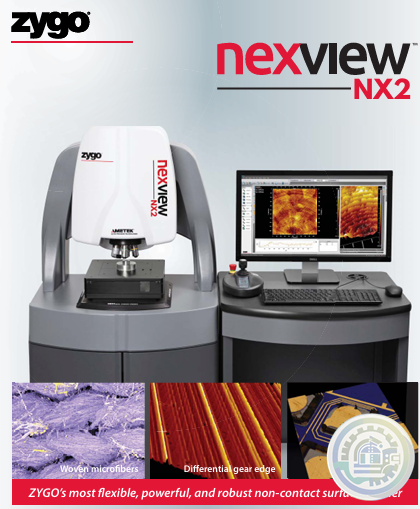 ZYGO’s most flexible, powerful, and robust non-contact surface profiler
 -
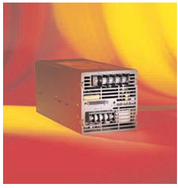 Pioneer Magnetics MID VOLTAGE 12V TO 60V AC TO DC SINGLE OUTPUT
 -
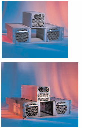 Pioneer Magnetics 3U POWERSHELF PRODUCT SERIES
 -
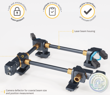 Scanlab Beam Alignment Module – BAM-G1
 -
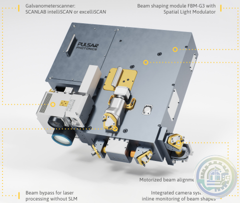 Scanlab FlexibleBeamShaper FBS-G3
 -
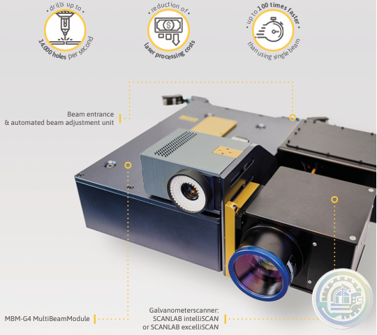 Scanlab MultiBeamScanner MBS-G4
 -
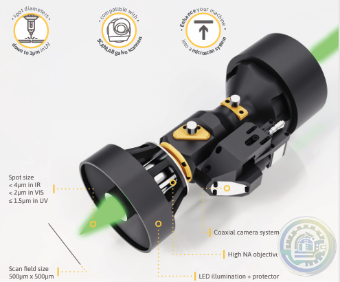 Scanlab Microscan Extension MSE-G2
 -
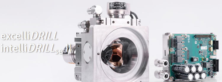 Scanlab excelliDRILL and intelliDRILLse II
 -
 Scanlab intelliDRILLse II – smart drilling
 -
 Scanlab excelliDRILL – high performance drilling
 -
 Scanlab XL SCAN SCANmotionControl
 -
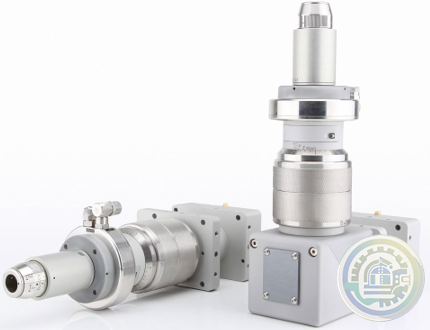
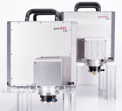 Scanlab precSYS micromachining sub system
 -
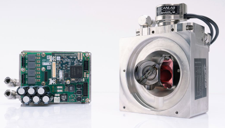
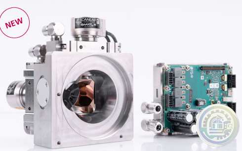
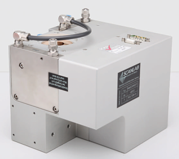 Scanlab WelDYNA Scan Head
 -
 Scanlab Collimation Module
 -
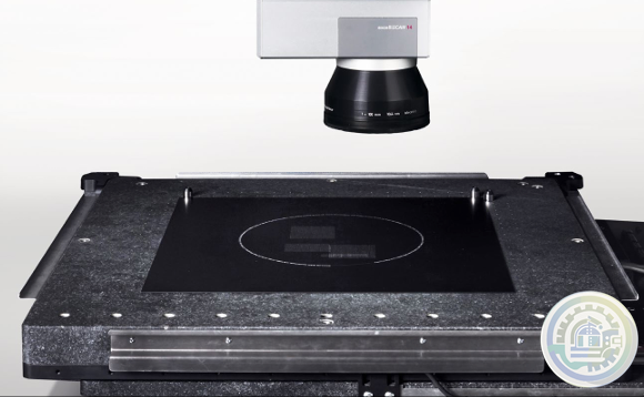
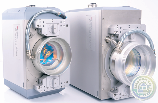 Scanlab intelliWELD 3D scan systems
 -
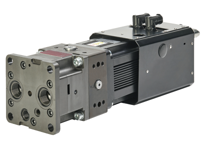 MOOG ELECTROHYDROSTATIC PUMP UNIT WITH INTERNAL GEAR PUMP (EPU-G)
 -
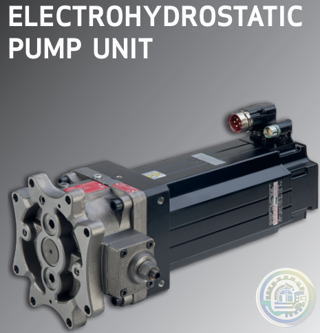 MOOG Electrohydrostatic Pump Unit
 -
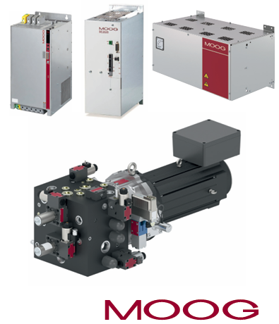 MOOG ENERGY MANAGEMENT SYSTEM (EMS) FOR EAS
 -
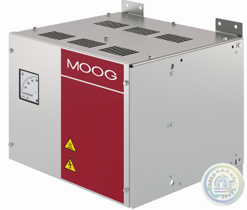 MOOG ESU-C Energy Management System
Please do not listen to the advice of non-professional engineers! Cause equipment damage!


wechat/whatsapp:
+86-181-44100-983
Email: kongjiangauto@163.com
-
ABB SCC-C 23070-0-10121210 Sample Gas Cooler
-
ABB OTM100F4C20D380C MOTORIZED CHANGE-OVER SWITCH
-
ABB Pluto S46 v2 Programmable safety controller
-
ABB Pluto O2 Programmable safety controller
-
ABB Pluto D45 Programmable safety controller
Copyright © 2009 - 2024 Cld , All Rights Reserved K-JIANG All rights reserved