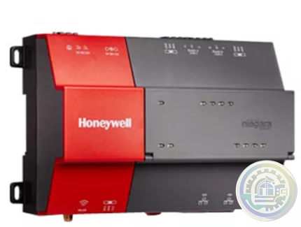
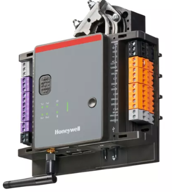
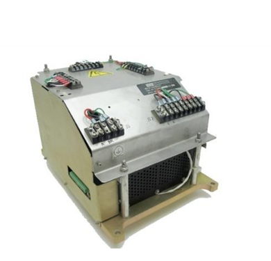
-
Kollmorgen AKT2G-AC-FAN-001 fan cartridge
-
Kollmorgen AKT-AN-820-000 8-Channel Analog Input Terminal
-
Kollmorgen 4-Channel Analog Input Terminal (AKT-AN-420-000)
-
METSO D201379 PC Board PLC & ADD-ON Board
-
Metso PDP403 Distributed Processing Unit
-
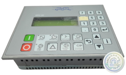
Alfa Laval EPC 60 Retrofit kit
-
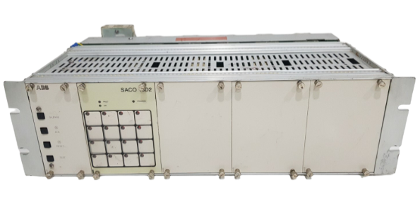
ABB Digital annunciator unit SACO 64D4
-
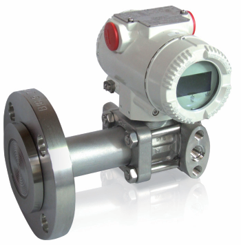
ABB Model 264DD Differential/Gauge
-
ABB Alarm annunciators
-
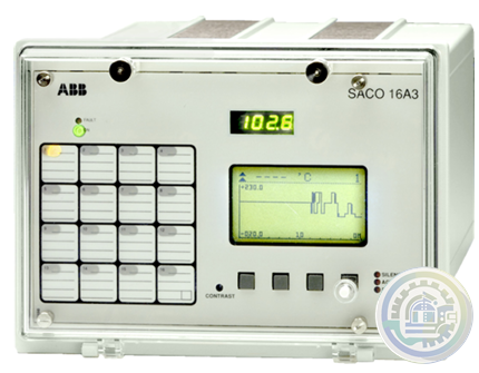
ABB SACO 16 A3 Analog Annunciator Unit
-
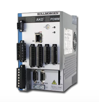
Kollmorgen AKD PDMM® Programmable Drive, Multi-Axis Master
-
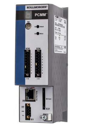
Kollmorgen PCMM: Programmable Controller, Multi-Axis Master
-
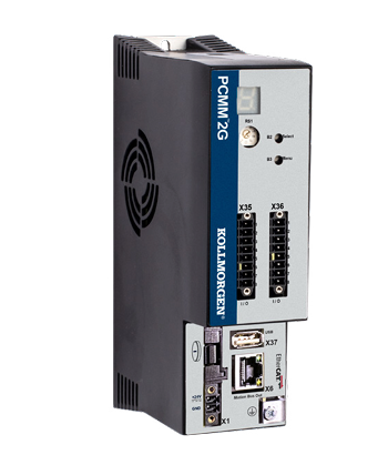
Kollmorgen PCMM2G: Next-Generation Performance in a Powerful, Compact Controller
-
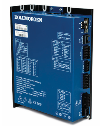
Kollmorgen P80630 Stepper Drive
-
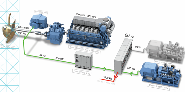
Kongsberg Maritime System and vessel conversions
-
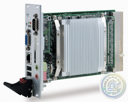
ADLINK CPCI-3840 3U CompactPCI Intel® Pentium® M Processor Module
-
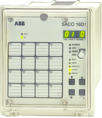
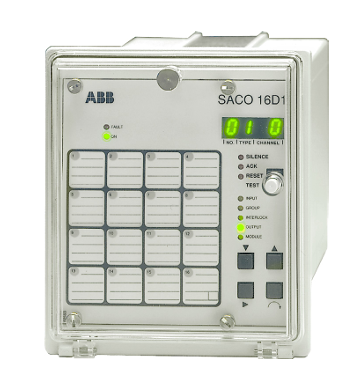
ABB Digital Annunciator Unit SACO 16D1
-
ABB SACO16D1-AA Digital Annunciator Unit
-
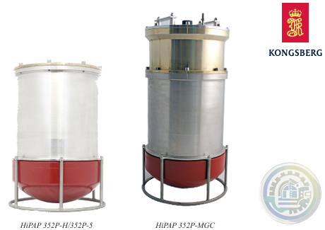
Kongsberg HIPAP® 352P PORTABLE HIGH PRESICION ACOUSTIC POSITIONING
-
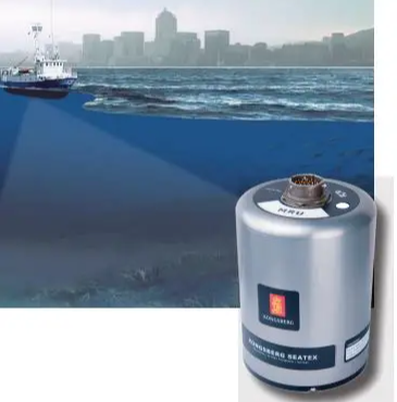
Kongsberg MRU 5 Motion Reference Unit
-
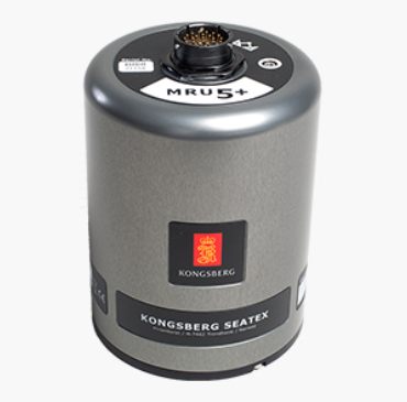
Kongsberg MRU 5+ Motion Reference Unit
-
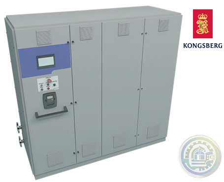
Kongsberg KONGSBERG MARITIME PROPULSION SYSTEMS Active Front End (AFE)
-
Kongsberg HiPAP 352P Portable acoustic positioning system
-
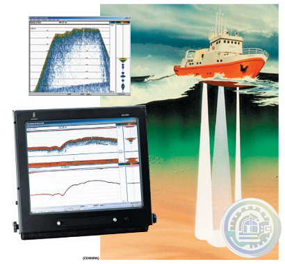
Kongsberg EA600 New generation precision hydrographic echo sounder
-
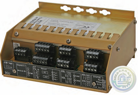
Kongsberg Digital Governor Unit (DGU) AutoChief® 600
-
Kongsberg AutoChief® 600 Propulsion Control System
-
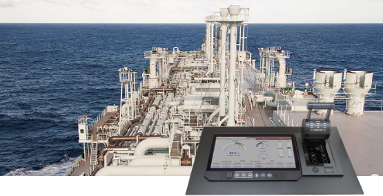
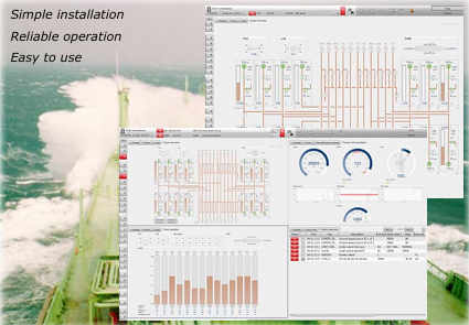
Kongsberg K-Chief Vessel Automation System
-
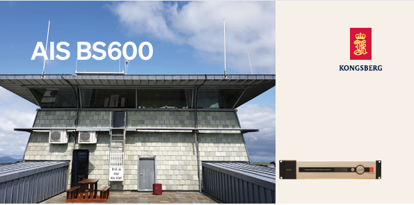
Kongsberg AIS BS600 Automatic Identification System - Base Station
-
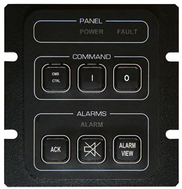
Kongsberg K-Chief 600 Alarm and Command Panel
-
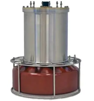
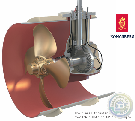
Kongsberg Tunnel Thrusters Type TT FP
-
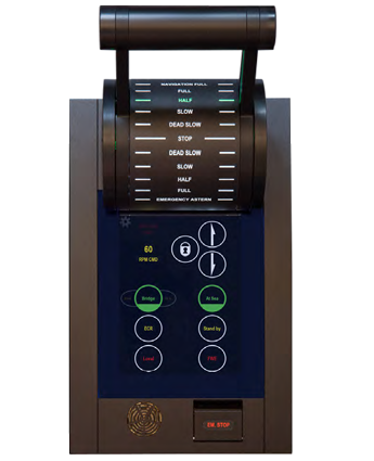
Kongsberg AutoChief®600 Lever Telegraph Unit (LTU11)
-
YOKOGAWA Model AW810D Wide Area Communication Router
-
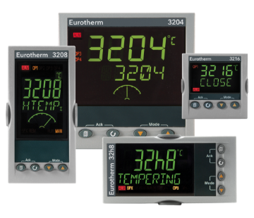
Watlow Eurotherm® 3200 Temperature/Process Controller
-
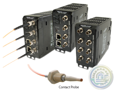
Watlow EtherCAT®, Fiber Optic Temperature Measurement and Control System
-
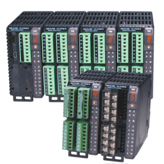
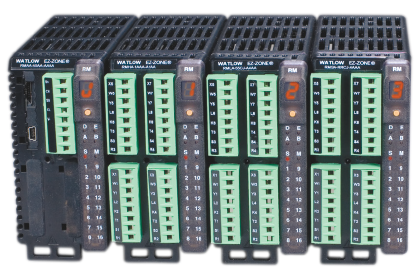
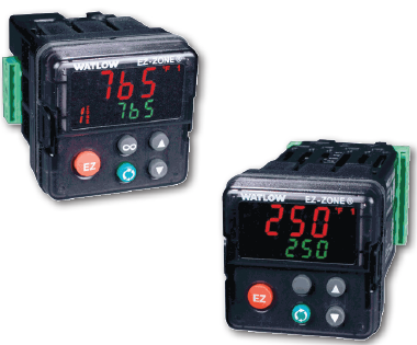
Watlow EZ-ZONE® RM Modular Controller Family
-
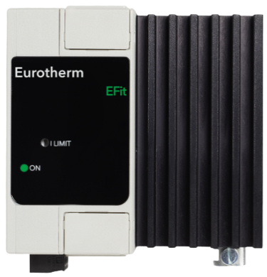
Watlow EFit SCR Power Controller
-
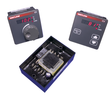
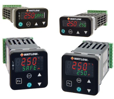
Watlow Basic Temperature and Limit Controllers
-
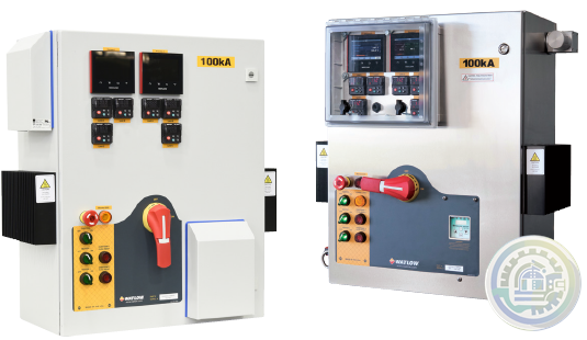
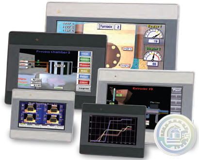
Watlow’s New WATCONNECT® Control Panels
-
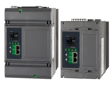
Watlow EPack-2PH Compact SCR Power Controllers
-
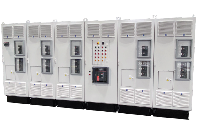
Watlow Large and Extra-Large WATCONNECT® Panels
-
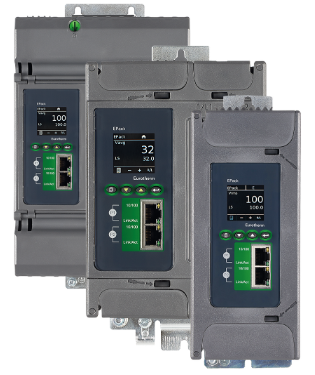
Watlow Eurotherm® EPack™ compact SCR power controllers-1PH -2PH -3PH
-
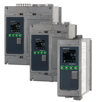
Watlow Eurotherm® EPack™ Lite Compact SCR Power Controllers
-
Watlow EPack™ Lite-1PH Compact SCR Power Controllers
-
Watlow’s new SERIES LS offers fixed limit set point temperature values
-
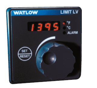
Watlow The SERIES LV limit family
-
Watlow’s family of microprocessor- based limit controllers SERIES LF
-
Watlow The EZ-ZONE RM controller simplifies thermal system management
-
Watlow The PM LEGACY™ series panel mount controller
-
Watlow EZ-ZONE® Remote User Interface (RUI)
-
Watlow Silver Series EM Operator Interface Terminal
-
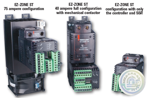
The EZ-ZONE® ST integrated solid state controller from Watlow®
-
YOKOGAWA Cooling Water Pump Failure Prediction Monitoring
-
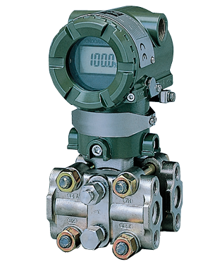
YOKOGAWA EJA Series Differential Pressure and Pressure Transmitters
-
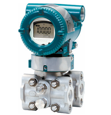
YOKOGAWA EJA110E Diff erential Pressure Transmitter
-
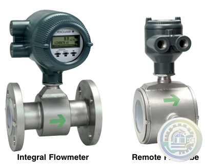
YOKOGAWA AXF Magnetic Flowmeter Series
-
YOKOGAWA Turbomachinery Controller Overview (FCN-500/FCN-RTU)
-
YOKOGAWA STARDOM FCN-RTU Autonomous Controller
-
YOKOGAWA FCN Autonomous Controller Hardware (FCN-100)
-
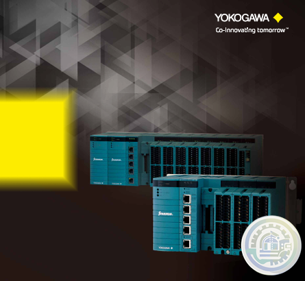
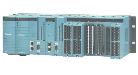
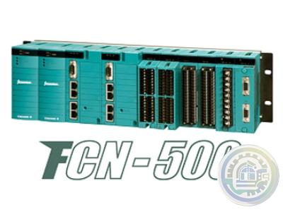
YOKOGAWA STARDOM FCN-500 Autonomous Controller
-
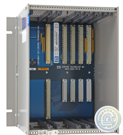
CTI 2500-R4 Four-Slot Base with High-Speed Channel
-
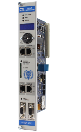
CTI 2500P-J750 Janus PAC with 3MB Project Memory
-
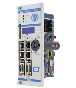
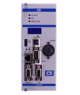
CTI 2500C-J750“Janus”Compact Programmable Automation Controller
-
CTI 2500 Series® Compact Programmable Controllers
-
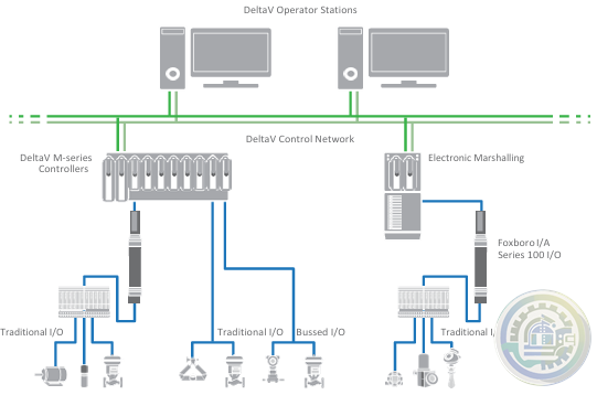
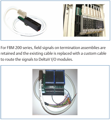
Emerson DeltaV™ Flex.Connect Solutions for Foxboro™ I/A Series 100 I/O
-
Emerson Modernization of Foxboro I/A Series® Systems to the DeltaV™ System
-
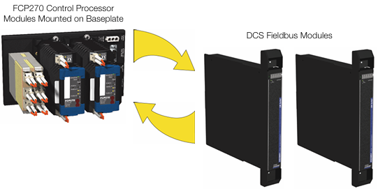
Foxboro DCS Fieldbus Modules for APACS+™ Automation Systems
-
Foxboro Evo™ Process Automation System
-
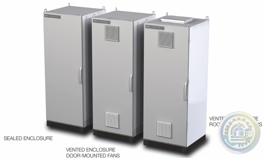
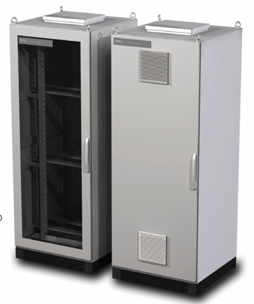
Foxboro™ DCS G61 Tricon Termination Enclosure
-
Foxboro G60 Tricon System Enclosure I/A Series® HARDWARE
-
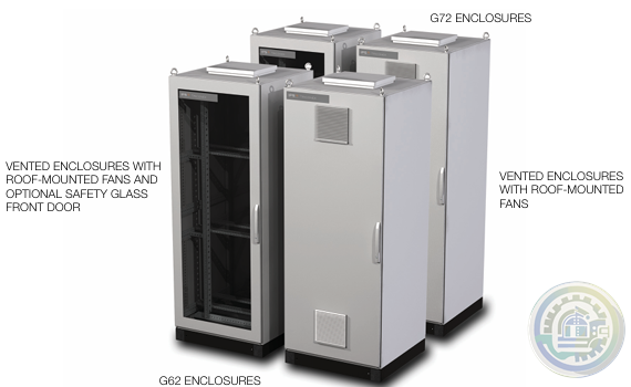
Foxboro G62 and G72 Tricon System and Termination Enclosures
-
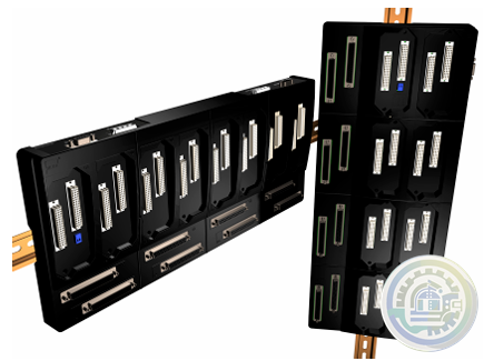
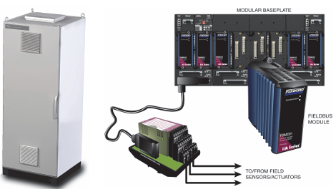
Foxboro I/A Series® Hardware DIN Rail Mounted Fieldbus Module Baseplate
-
Kongsberg K-Chief 600 Marine automation system
-
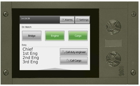
Kongsberg WCC 600 Watch Call Panels
-
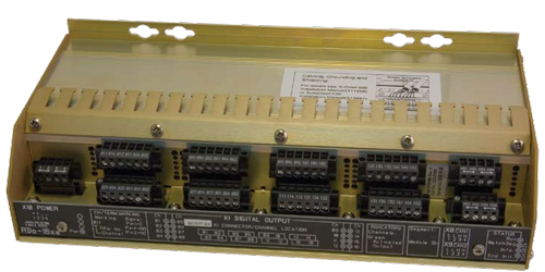
Kongsberg Distributed Processing Units Remote Digital Output (RDo-16xe)
-
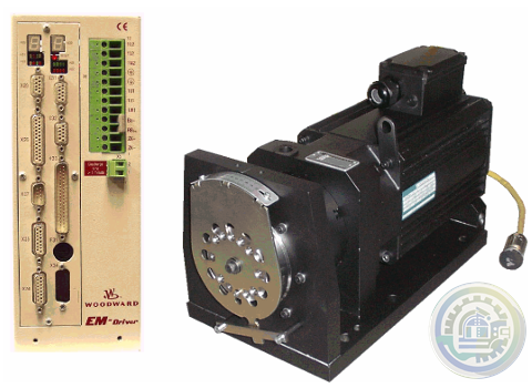
Woodward EM‐80 and EM‐300 Actuators All‐Electric Actuator System
-
Foxboro DCS FBM for Migration of Bailey® Systems
-
Foxboro Migration with FCP280 and DCS FBMs
-
Foxboro DCS Fieldbus Modules for Siemens APACS+™ Automation Systems
-
Foxboro 200 Series Baseplate Module Mounting
-
Foxboro Standard 200 Series Subsystem Overview
-
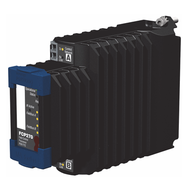
Foxboro Field Control Processor 270 (FCP270)
-
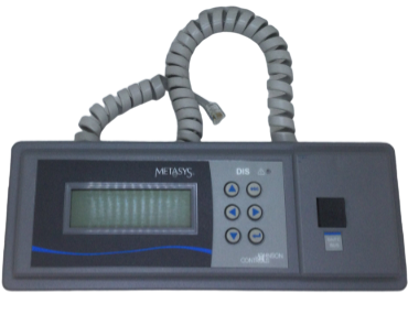
Johnson Controls DIS1710 Local Controller Display Installation Instructions
-
Johnson Controls FX-DIS Local Controller Display
-
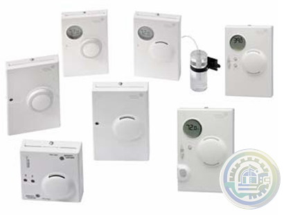
Johnson Controls WRZ Series Wireless Room Sensors
-
Woodward EM-80/EM-300 Actuator System
-
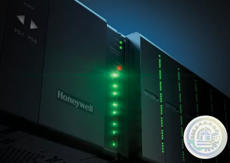
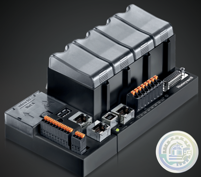
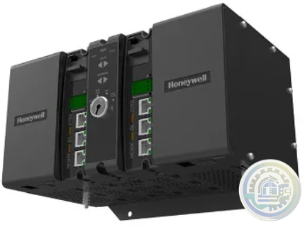
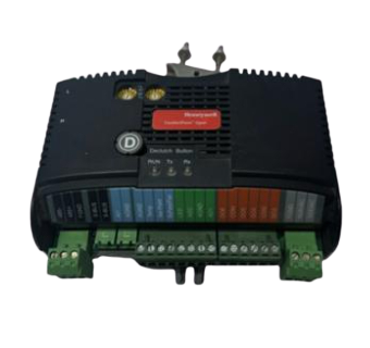
Honeywell ControlEdge™ PLC Modular Controllers
-
Honeywell CONTROLEDGE PCD Compact, Cyber Secure Control System
-
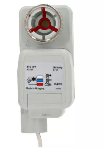
Honeywell M6410A, M7410F Non-Spring Return Cartridge Globe Valve Actuator
-
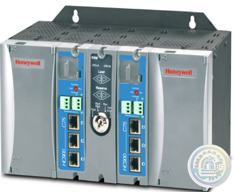
Honeywell ControlEdge™ HC900 How Does It Work?
-
Honeywell ControlEdge HC900 controller
-
Honeywell HC900 Functional Overview
-
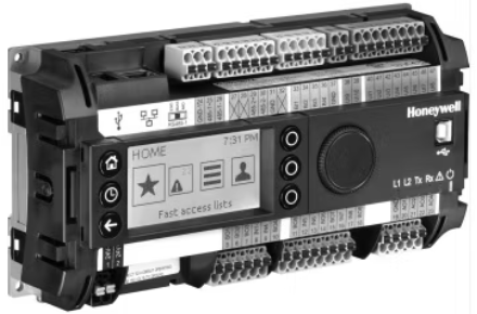
Honeywell Optimizer Advanced Controllers are a family of next generation integration & plant controllers
-
Honeywell Optimizer Advanced Controller
-
Honeywell Excel Web II Control System
-
Honeywell CPO-PLANT Controller area of the site
-
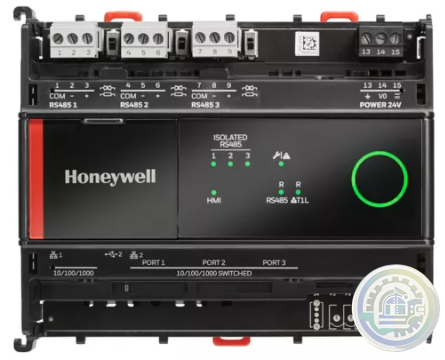
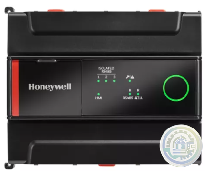
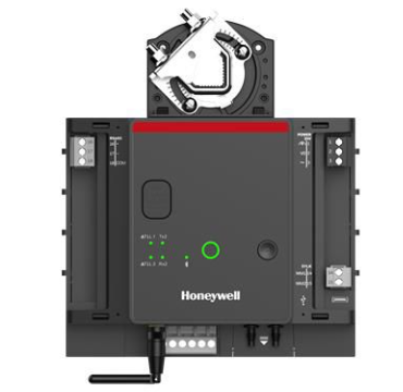
Honeywell ComfortPoint Niagara T1L VAV Controller
-
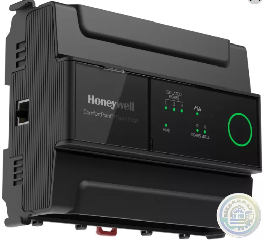
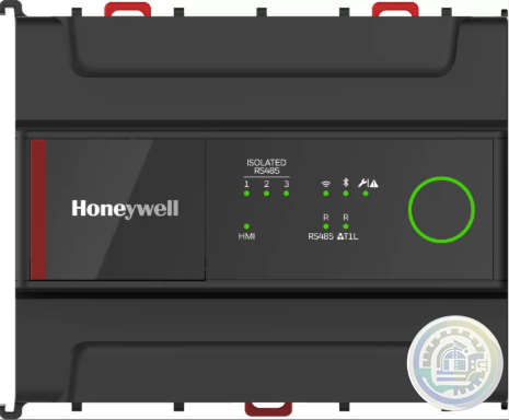
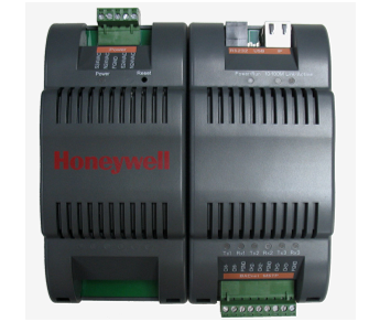
Honeywell ComfortPoint™ Open Plant Controller
-
Honeywell ComfortPoint Open CP-EXPIO (EXPANSION IO BOARD)
-
Honeywell ComfortPoint Open CPO-VAV2A-US (UNITARY CONTROLLER)
-
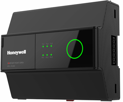
Honeywell ComfortPoint™ Open CPO-PC400 Plant Controller
-
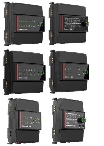
Honeywell I/O MODULES EXPANSION MODULES & WIRING ADAPTER
-
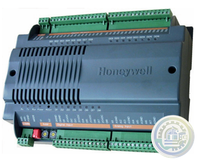
Honeywell CPO-DIO ComfortPoint Open (DIGITAL I/O CONTROLLER)
-
Honeywell CP-Core ComfortPoint Open
-
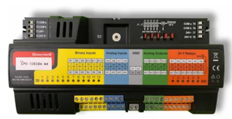
Honeywell CPO-IO830A ComfortPoint Open MIXED I/O MODULE
-
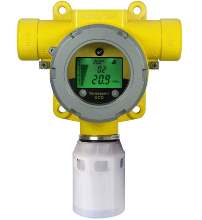
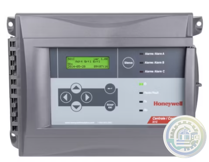
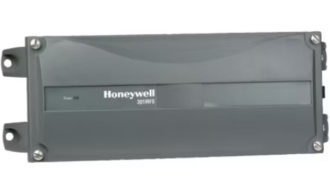
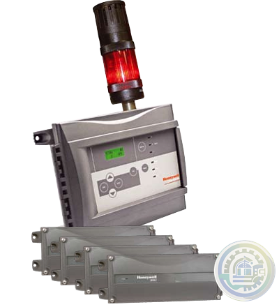
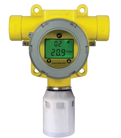
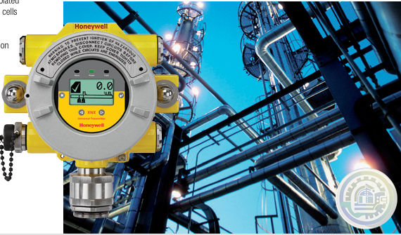
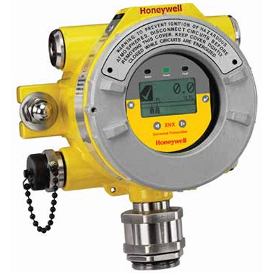
Honeywell Sensepoint XCD
- Baldor
- Glassman
- Johnson Controls
- Studer
- Watlow
- AEG
- ADVANCED
- KEBA
- Bristol Babcock
- Rolls-Royce
- Aerotech
- APPLIED MATERIALS
- Basler
- SAACKE
- BENDER
- Kollmorgen
- MEGGITT
- METSO
- MITSUBISHI
- MTL
- HIMA
- Siemens
- BACHMANN
- AMAT
- DEIF
- DELTATAU
- EATON
- ELAU
- LAM
- SCHNEIDER
- Advantest
- ABB
- GE
- Emerson
- Motorola
- A-B
- KUKA
- Abaco
- HITACHI
- SST
- Vibro-Meter
- Rexroth
- Prosoft
- DFI
- Scanlab
- Reliance
- Parker
- Woodward
- MOOG
- NI
- FOXBORO
- Triconex
- Bently
- ALSTOM
- YOKOGAWA
- B&R
- UNIOP
- KONGSBERG
- Honeywell
- Omron
- CTI
- EPRO
- Tell:+86-18144100983
- email:kongjiangauto@163.com
- Application:wind/ petroleum/ chemical/ natural gas/ Marine/ mining/ aviation/ electronics/ steel/ nuclear power/ electric power/ coking/ air separation and so on
- Series:PLC/ DCS/ servo/ analog/ Ethernet/ digital/ redundant module/ tension system/ excitation/ generator management/ human-machine interface/ detection card/ sensor/ AC drive/ etc
Cables and Connector Mates
Cables in several lengths are available from GE Fanuc for motor to controller connections and various other controller functions.
It is strongly recommended that you use the cables available from GE Fanuc as shown in Table 3-15.
GE Fanuc does not provide mating connectors for the MTR-Series motors or S-Series motors along with the motor;
you can, however, purchase the S-Series and MTR-3T Series motor connector kits,
shown in table 3- 16, from GE Fanuc.
Note: GE Fanuc cables and connectors shown are not rated for IP67 environments,
or washdown applications. GE Fanuc cables are not designed for high flex or cable track applications.
Analog Output (AO)
The hardware analog output is primarily used as a process input to the controller programs,
but it can also be used a diagnostic output for various signals used in the tuning and
debugging process. The Analog Common pin is used for the signal return. The Analog
Output (AO) software parameter allows you to configure this output to represent one of the
following signals:
• Actual velocity (AO = VLA)
• Actual output current (AO = CMD)
• Following error (AO = FE)

S-Series Servo Motor Encoder Wiring
Position feedback cables as shown in Table 3-15 are available from GE Fanuc for the S2K
Series controllers. Plug the motor end of the encoder cable into the connector on the motor
and the DB-type connector end of the cable into the DB-15 socket labeled Position
Feedback on the front of the controller. The best system reliability is achieved when the
encoder cable is returned in a separate conduit from that housing the motor power cable.
The feedback cable should use 24-28 AWG twisted pair wire and must be shielded. The
shields must be terminated to the isolated ground pins on the Position Feedback (DB-15)
connector on the S2K controller as shown in Table 3-8. Maximum serial encoder cable
length is 15 meters using factory-supplied cables. If two parallel 24 AWG wires are
connected to both the +5v and ground (GND), as shown in Table 3-8, longer cable runs
require the wire gauge to be increased to reduce the signal voltage drop. The S-Series
motors require a 5V ±5% (4.75 to 5.25 VDC) power source for proper operation.

Stepper Controller Electrical Specifications
The S2K Stepper Controller (IC800STI105xx) is suitable for use on a circuit capable of
delivering not more than 5,000 rms symmetrical amperes and 130 volts maximum when
protected by RK5 class 15A fuses. Table 2-2 summarizes the Stepper Controllers
maximum continuous input power requirements. The actual input power and current is a
function of the motor's operating point and the duty cycle.
INDUCTIVE LOAD DRIVER — Bifilar (unipolar) stepper motors can be driven directly.
The internal kickback diodes prevent damage to the output transistors by suppressing the high-voltage spikes which occur when
turning OFF an inductive load.
We have the same series of models in stock.
If you don't find the model you need, please contact us and we will provide you with an official quotation!
GE Fanuc IC800SLCFLYZ030 Flying Lead Cable |
GE Fanuc IC800SLCBVL100 Power/Brake Cable |
GE Fanuc IC800SLCBZ050 Brake Cable |
GE Fanuc IC800SLCBZ100 Brake Cable |
GE Fanuc IC800SLCEV050 Encoder Cable |
GE Fanuc IC800SLCEV100 Encoder Cable |
GE Fanuc IC800SLCEZ050 Encoder Cable |
GE Fanuc IC800SLCEZ100 Encoder Cable |
GE Fanuc IC800SLCFLYV030 Flying Lead Cable |
GE Fanuc IC800SLCFLYZ010 Flying Lead Cable |
GE Fanuc IC800SLCPV050 Power Cable |
GE Fanuc IC800SLCPZ050 Power Cable |
GE Fanuc IC800SLCPVL100 Power Cable |
GE Fanuc IC800SLCPVL050 Power Cable |
GE Fanuc IC800SLCPV100 Power Cable |
GE Fanuc IC800SLCIZ010 Interface Cable |
GE Fanuc IC800SLCIV010 Interface Cable |
GE Fanuc IC800SLCIV030 Interface Cable |
GE Fanuc IC800SLCBVL050 Power/Brake Cable |
GE Fanuc IC800SLCIZ030 Interface Cable |
| User name | Member Level | Quantity | Specification | Purchase Date |
|---|


Please do not listen to the advice of non-professional engineers! Cause equipment damage!


wechat/whatsapp:
Email: kongjiangauto@163.com
-
Vibro-meter vmf-RLC16-V111 200-570-101-015 200-570-000-111 Relay Card
-
Vibro-meter vmf-IOC4T 200560-101-017 200-560-000-111 I/O module
-
vmf cpum vmf-cmc16 200-530-111-013 200-530-100-014 Vibro-meter Monitoring system Modulee
-
Vibro-meter 200-595-045-114 | CPUM | Vibration Processor Module
-
Vibro-meter SIM-275A 200-582-500-013 state-of-the-art protection and monitoring module
Copyright © 2009 - 2024 Cld , All Rights Reserved K-JIANG All rights reserved


