-
Deif Du-2 / Mkiii Multil neas Ppm Protecci n Y Gesti n de Energ a 100-690vac
-
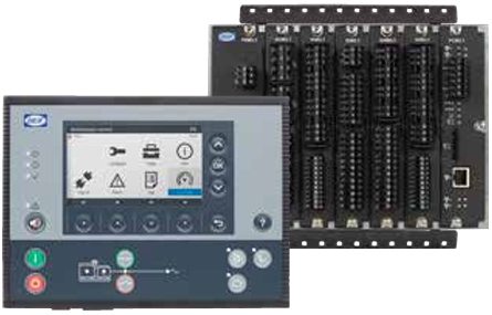
DEIF AGC 222 & IOM 220 advanced genset controller
-
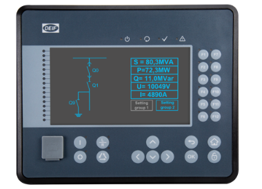
Deif Delomatic 4 DGU 0005 Generator Control System PCM 4-1, IOM 4-1, SCM 4-2
-
DEIF PPM-3-DG PROTECTION AND POWER MANAGEMENT MEAS.VOLTAGE:100-690VAC, 0.5MA
-
DEIF AGC Plant Management (Genset Controller) 100132445.10
-
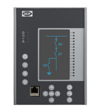
DEIF MVR-F205 Directional Feeder Protection
-
DEIF Protection & power management PPM 300 Features
-
DEIF PPM 300 Protection & power management
-
DEIF The series of switch mode power supplies
-
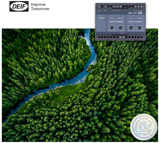
DEIF The RMC-142D is CE-marked and is applied for protection of voltage sources
-
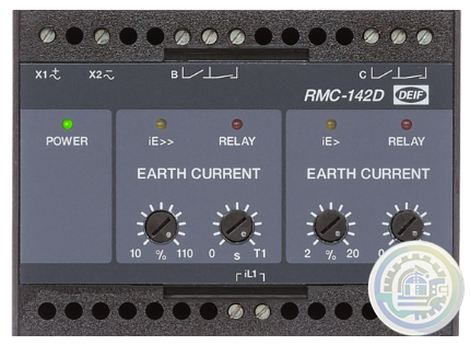
DEIF RMC-142D Current relay
-
DEIF The GPU-3 Hydro is well-suited for PLC-controlled systems
-
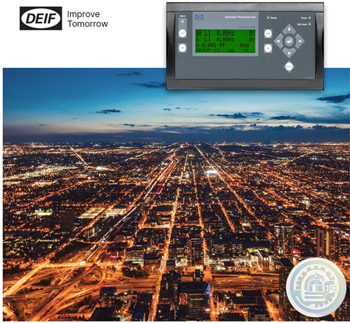
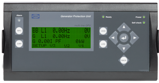
DEIF GPU-3 hydro Generator protection unit
-
DEIF MVR-200 series Medium Voltage Relay
-
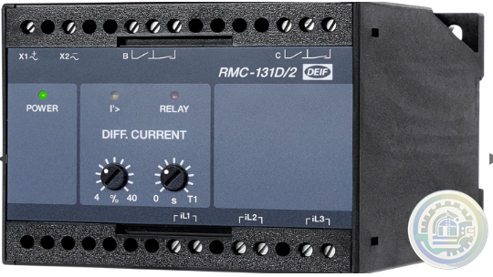
DEIF RMC-131D Current relay
-
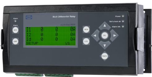
DEIF MDR-2 Multi-differential relay
-
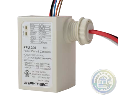
IR-TEC PPU-300 Power Pack & Controller
-
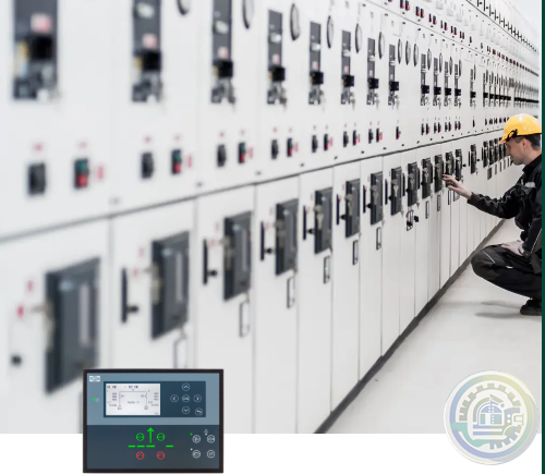
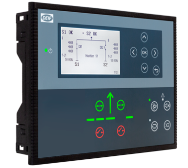
Streamline power transfer with DEIF's AGC 150 ATS controller
-
DEIF AGC 150 ATS: Advanced Generator Transfer Switch for Seamless Power Management
-
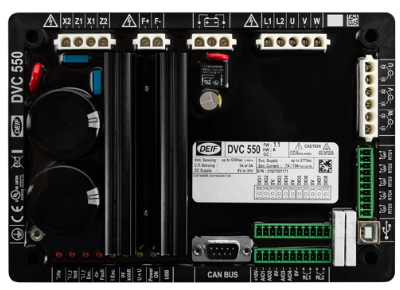
DEIF DVC 550 Automatic voltage control
-
DEIF Optimize Your Power Systems with DEIF's DVC 550
-
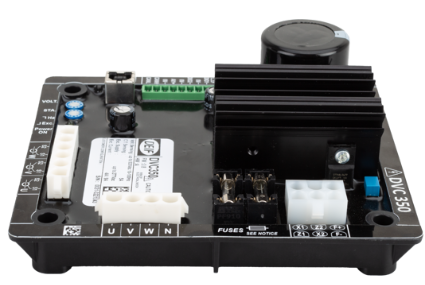
DEIF DVC 350 Digital automatic voltage regulator (AVR)
-
DEIF Advanced Features of DVC 350 Digital Automatic Voltage Regulator
-
DEIF Digital Voltage Controller DVC 550
-
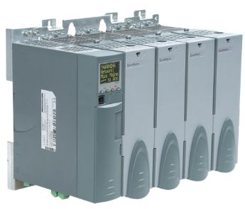
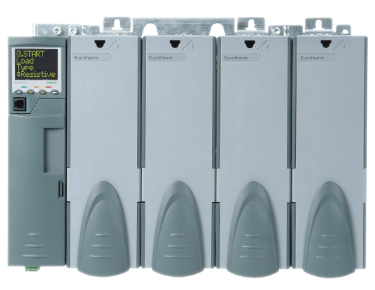
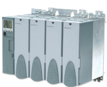
Watlow EPower™ Controller Revolutionary modularity and configurability to meet your needs
-
Watlow Eurotherm® EPower™ Controller
-
Watlow Eurotherm A standardized upgrade solution
-
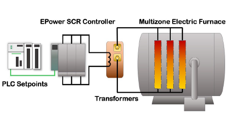
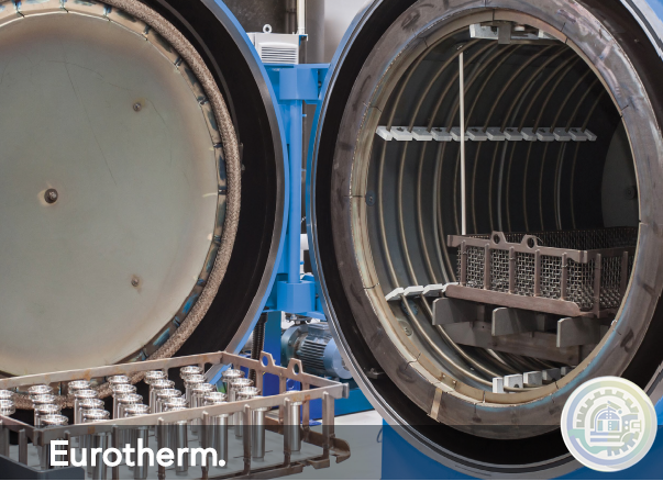
Watlow Eurotherm Cost efficiency for electric furnaces
-
Watlow Eurotherm Energy efficiency for electric heat treatment furnaces
-
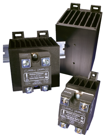
Watlow Solid State Relays (SSR)
-
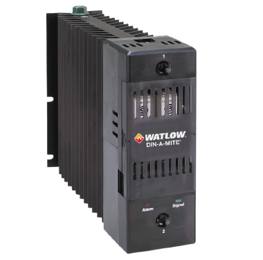
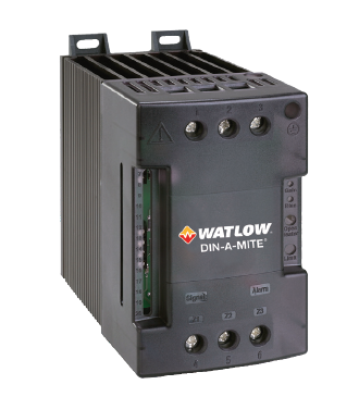
Watlow DIN-A-MITE® D silicon controlled rectifier (SCR) power controller
-
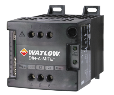
Watlow DIN-A-MITE® C silicon controlled rectifier (SCR) power controller
-
Watlow DIN-A-MITE® B Power Controller
-
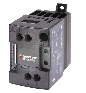
Watlow DIN-A-MITE® A Power Switching Devices
-
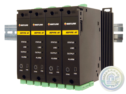
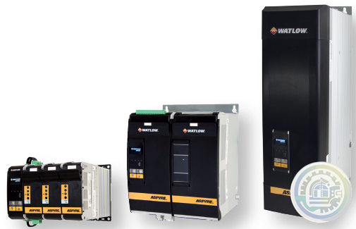
Watlow ASPYRE® AT Power Controllers
-
Watlow ASPYRE® DT SCR Power Controllers
-
Watlow PM PLUS™ Controller Features and Benefits
-
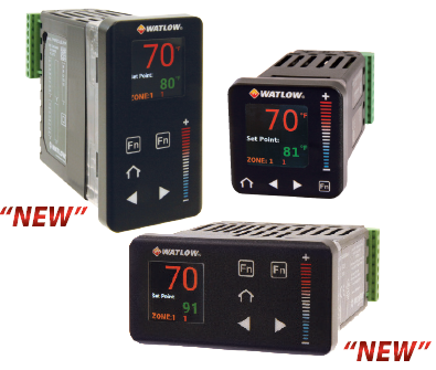
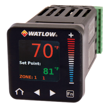
Watlow PM PLUS™ Controller
-
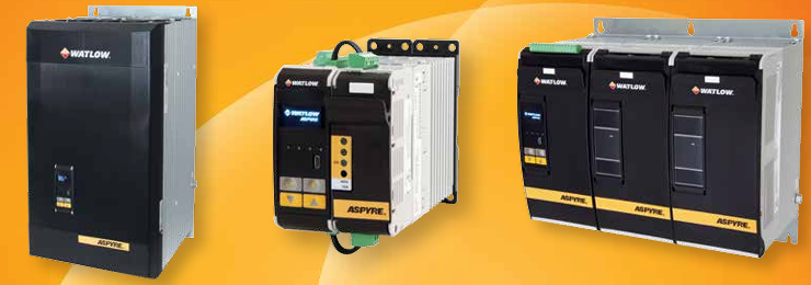
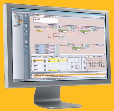
Watlow ASPYRE To Elevate Your System
-
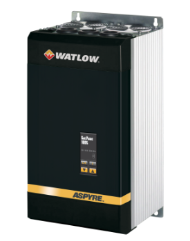
Watlow ASPYRE® DT Power Controllers
-
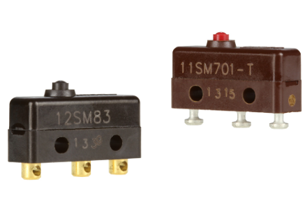
Honeywell MICRO SWITCH Premium Subminiature Basic Switches
-
HIMA SILworX API (application programming interface)
-
HIMA Automated testing with SILworX Smart Safety Test
-
HIMA SILworX The world’s most advanced safety application manager
-
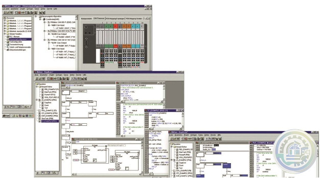
Eaton CODESYS software
-
Eaton CODESYS version 3 Integrated fieldbus configuration
-
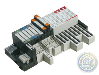
Eaton XI/ON I/O system
-
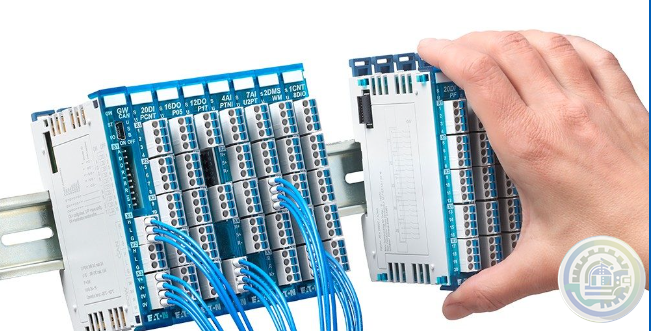
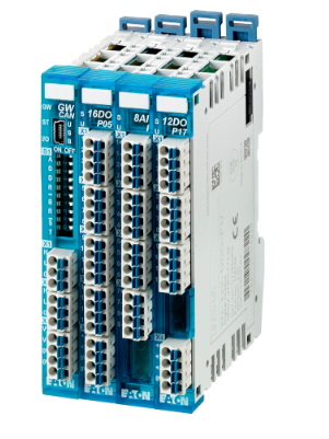
Eaton XN300 modules High modularity with a small footprint
-
Eaton XN300 I/O system
-
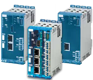
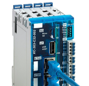
Eaton The XC300 modular PLC: Powerful communication
-
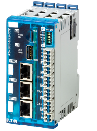
Eaton The three device variants of the XC300 Comprehensive functions and interfaces
-
Eaton XC300 modular programmable logic controllers
-
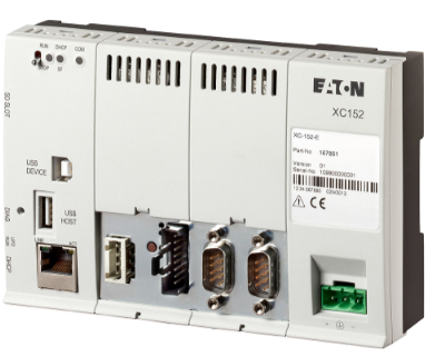
Eaton XC150 compact programmable logic controllers
-
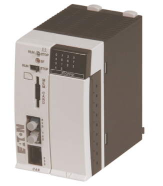
Eaton XC100/200 modular programmable logic controllers
-
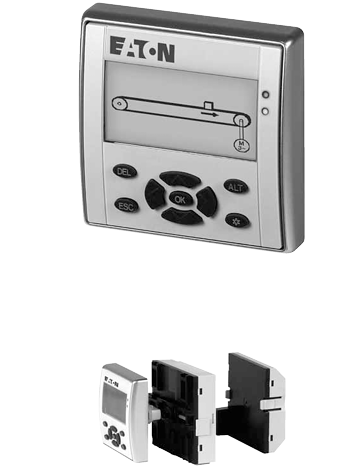
Eaton Multi-Function Display MFD-Titan
-
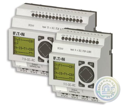
Eaton Legacy Easy programmable relays
-
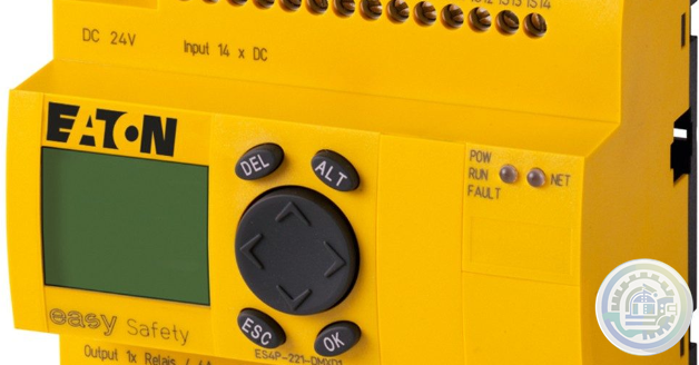
Eaton easySafety Safety for people and machines
-
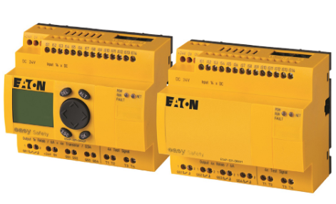
Eaton easySafety programmable safety relays
-
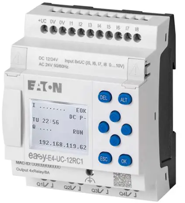
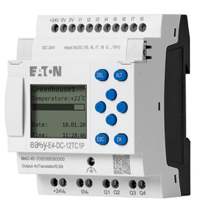
Eaton easyE4 programmable relays
-
Eaton easyE4 nano programmable logic controllers
-
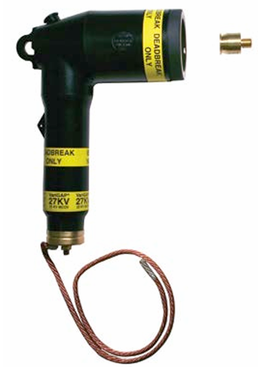
Eaton COOPER POWER SERIES DirectConnect elbow arrester
-
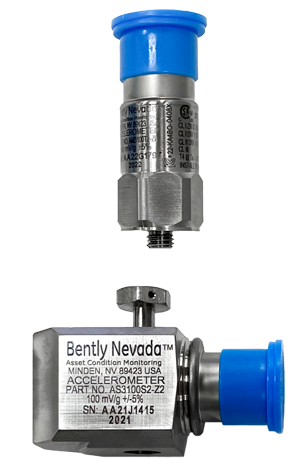
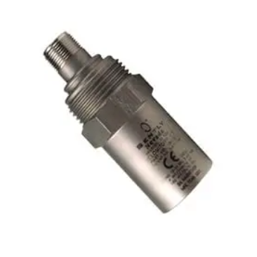
Bently Nevada IEPE Accelerometer Series
-
Bently Nevada Velocity Sensors & Accelerometers
-
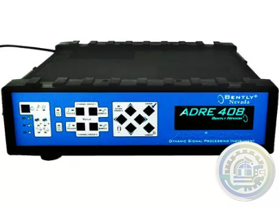
Bently Nevada ADRE - Data Acquisition & Machine Diagnostics System
-
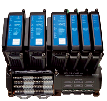
Bently Nevada 3701/55 Emergency Shutdown Device
-
Bently Nevada Asset Condition Monitoring
-
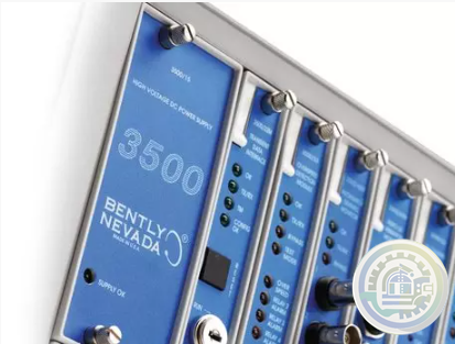
Bently Nevada 3500 Machinery Protection Systems
-
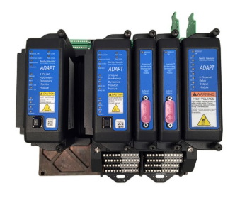
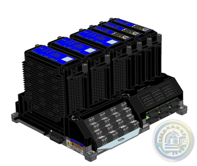
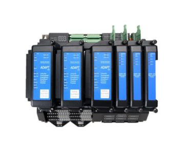
Bently Nevada ADAPT ESD Relay Module
-
Bently Nevada Typical (and recommended) applications of the ADAPT ESD
-
Bently Nevada 3701/55 ADAPT (ESD) Emergency Shutdown Device
-
Bently Nevada Online Condition Monitoring Systems
-
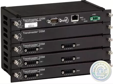
Bently Nevada Trendmaster Online Condition Monitoring System
-
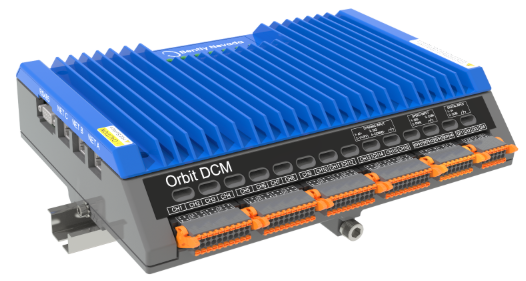
Bently Nevada Orbit Distributed Condition Monitoring
-
HIMA The HIJunctionBox is part of the Smart Safety Platform
-
HIMA HIJunctionBox Straightforward Safety
-
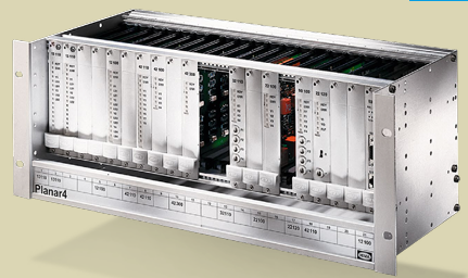
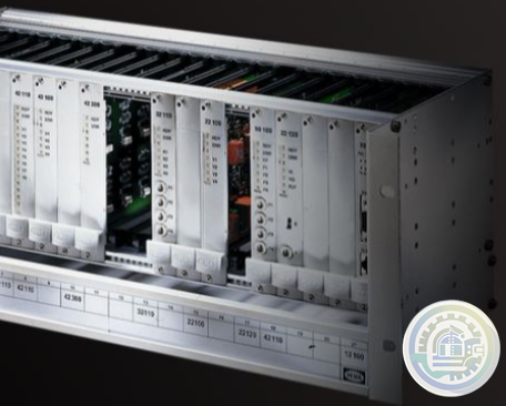
HIMA Planar4 Where Ultimate Safety Counts
-
HIMA HIQuad Lifecycle & Modernization
-
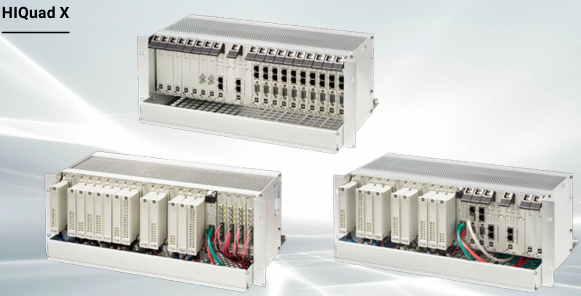
HIMA HIQuad X A New Dimension of Performance for Your Safety System
-
HIMA Communication Features of HIQuad X
-
HIMA Flexible SIL 4 Controllers SYSTEM FOR THE RAIL INDUSTRY
-
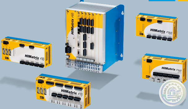
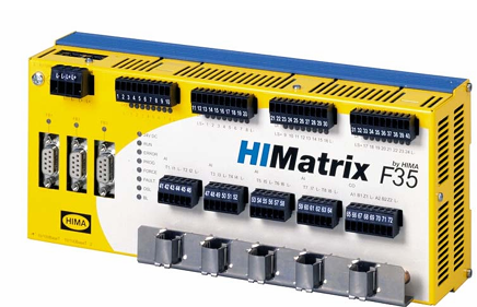
HIMA HIMatrix SYSTEMS Uniquely Fast, Uniquely Flexible
-
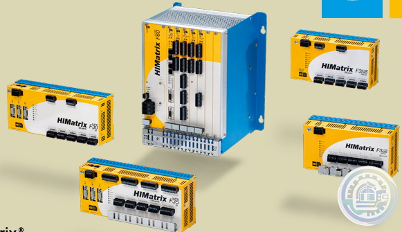
HIMA F35 HIMatrix Safety-Related Controller
-
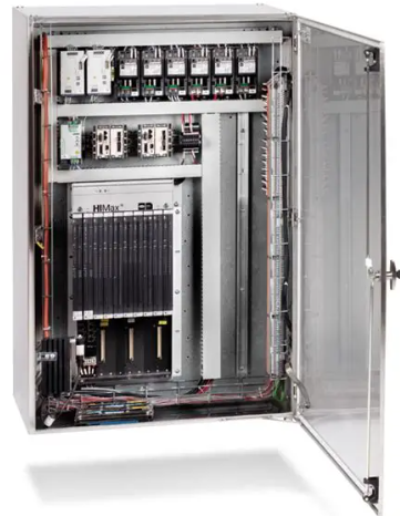
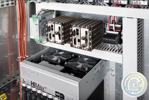
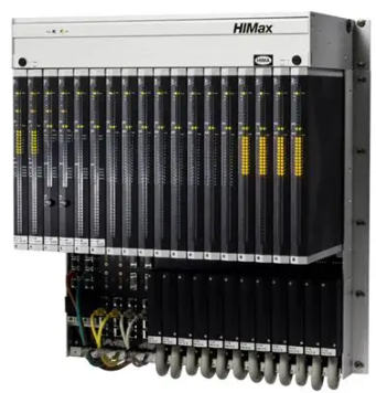
HIMA HIMax Flexible Safety for Maximum Profitability
-
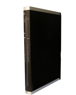
HIMA X-COM 01 Communication Module
-
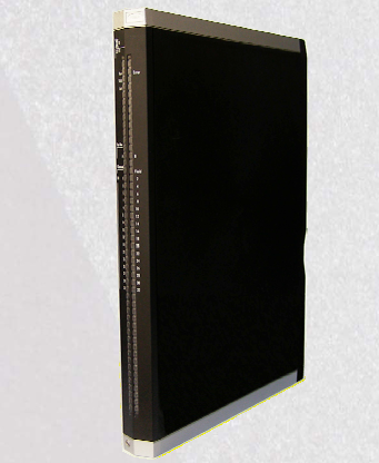
HIMA X-DI 64 01 Digital Input Module
-
Woodward Oil Management
-
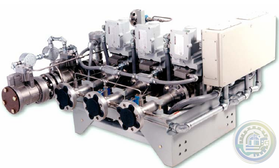
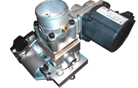
Woodward SonicFlo™ Gas Fuel Control Valve With Electric Trip
-
Woodward SonicFlo™ Gas Triple Coil Electrohydraulic Servo Valve Assembly
-
Woodward SonicFlo™ Gas Valves Hydraulically Actuated
-
Woodward Discrete Output for Driver Status Indication
-
Woodward PWM Input for Position Demand
-
Woodward The Swift valve is a sonic flow-metering valve
-
Woodward Swift™ Gas Metering System
-
Woodward LQ6 Liquid Fuel Valve with On‐board Driver
-
Woodward Fuel Metering System Integration Capabilities
-
Woodward DLE/DLN for Aeroderivative Turbine Platforms
-
Woodward Fuel Metering Systems
-
Woodward PG-07 controls Sequential spark ignition
-
Woodward PG-07 CONTROL SYSTEM FEATURES
-
Woodward PG-07 Power Generation & Stationary Control System
-
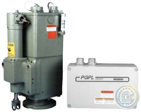
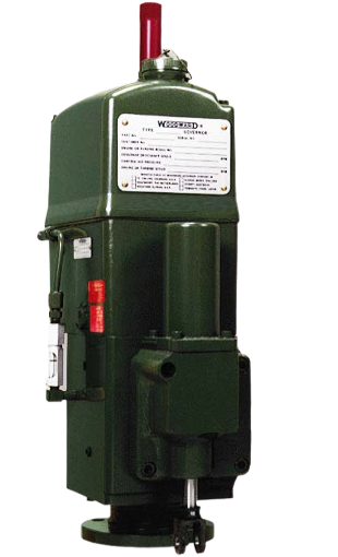
Woodward PG‐PL Governor
-
Woodward Air Management
-
Woodward Engine Actuation Systems
-
Woodward Fuel Injection and Ignition Systems
-
Woodward Fuel Control Systems
- Glassman
- Johnson Controls
- Studer
- Watlow
- AEG
- ADVANCED
- KEBA
- Bristol Babcock
- Rolls-Royce
- Aerotech
- APPLIED MATERIALS
- Basler
- SAACKE
- BENDER
- Kollmorgen
- MEGGITT
- METSO
- MITSUBISHI
- MTL
- HIMA
- Siemens
- BACHMANN
- AMAT
- DEIF
- DELTATAU
- EATON
- ELAU
- LAM
- SCHNEIDER
- Advantest
- ABB
- GE
- Emerson
- Motorola
- A-B
- KUKA
- Abaco
- HITACHI
- SST
- Vibro-Meter
- Rexroth
- Prosoft
- DFI
- Scanlab
- Reliance
- Parker
- Woodward
- MOOG
- NI
- FOXBORO
- Triconex
- Bently
- ALSTOM
- YOKOGAWA
- B&R
- UNIOP
- KONGSBERG
- Honeywell
- Omron
- CTI
- EPRO
- Tell:+86-18144100983
- email:kongjiangauto@163.com
- Application:wind/ petroleum/ chemical/ natural gas/ Marine/ mining/ aviation/ electronics/ steel/ nuclear power/ electric power/ coking/ air separation and so on
- Series:PLC/ DCS/ servo/ analog/ Ethernet/ digital/ redundant module/ tension system/ excitation/ generator management/ human-machine interface/ detection card/ sensor/ AC drive/ etc
FAULT CONDITIONS — In the event of a shortedload, shorted winding, or stalled motor, the load current will attempt to increase.
As described above, the drive current to the output stage is diverted (limiting the load current to about1 A), causing the output stage to go linear. As the junction
temperature of the output stage increases, the thermal limit circuit will become operational, further decreasing the drivecurrent.
The load current (junction temperature) is then a function of ambient temperature, state of remaining drivers,supply voltage, and load resistance.
If the fault condition is corrected, the output driver will return to its normal saturated condition.
Short circuit protection is provided for each output for supply voltages up to 25 V.
Any program can start and stop any other program, and all programs can utilize common motion blocks.
Engineering time is reduced and integration is simplified due to configuration and programming wizards for the controller software.

The controller has a simple diagnostic system that is displayed on a 2-character LED on the front panel.
INDUCTIVE LOAD DRIVER — Bifilar (unipolar) stepper motors can be driven directly.
The internal kickback diodes prevent damage to the output transistors by suppressing the high-voltage spikes which occur when
turning OFF an inductive load.
Enable Input
The Enable discrete input allows the host controller to enable or disable the power output
stage of the controller and reset faults. The Enable input must be active to run the servo
motor. This Enable hardware input works in tandem with a logical (software) enable register
called the Power Output Stage Enable (POE) register. The POE register will allow current to
flow into the motor only when set true and no faults are present on the controller. Since a
Lost Enable (LE) fault is generated when this hardware enable input is false, ensure that
POE=1. the hardware enable input is true, and all faults have been cleared (RSF register) to
activate the power stage of the controller.
The current state of the Enable input can be queried using the Fault Code (FC) register in
the terminal window. The Enable input should be connected as shown in the connection
diagrams in Section 3.6.10. The internal schematic for the enable input circuit is shown below.

Analog Output (AO)
The hardware analog output is primarily used as a process input to the controller programs,
but it can also be used a diagnostic output for various signals used in the tuning and
debugging process. The Analog Common pin is used for the signal return. The Analog
Output (AO) software parameter allows you to configure this output to represent one of the
following signals:
• Actual velocity (AO = VLA)
• Actual output current (AO = CMD)
• Following error (AO = FE)

The output can also be forced to a specific voltage value by setting the AO parameter to the
desired voltage from a program, PC terminal emulator, or Motion Developer terminal
window. The analog Output value can be queried in the terminal window using the “?” command.
Use 20-28 AWG twisted-pair wire with an overall shield for this signal interface. For best
noise immunity connect the shield to the Analog Common pin on the Auxiliary I/O connector.
The internal schematic for the analog output circuit is shown below.
We have the same series of models in stock.
If you don't find the model you need, please contact us and we will provide you with an official quotation!
GE IC800SSD107S1-CC VersaMotion S2K controller |
GE IC800SSI107S1-CE S2K Series SERVO DRIVE |
GE IC800SSI107D2-CE S2K Series Standalone Motion Controller |
GE IC800SSI107P2-CE VersaMotion S2K controller |
GE IC800SSD107RS1-CC VersaMotion S2K controller |
GE IC800SSI107RS1-CE S2K Series Standalone Motion Controller |
GE IC800SSI107RD2-CE VersaMotion S2K controller |
GE IC800SSI107RP2-CE VersaMotion S2K controller |
GE IC800SSD216S1-EC S2K Series Standalone Motion Controller |
GE IC800SSI216D2-EE VersaMotion S2K controller |
GE IC800SSI216P2-CE S2K Series Standalone Motion Controller |
GE IC800SSD216RS1-EC VersaMotion S2K controller |
GE IC800SSI216RD2-CE S2K Series Standalone Motion Controller |
GE IC800SSI216RP2-CE VersaMotion S2K controller |
GE IC800SSD228S1-CC VersaMotion S2K controller |
GE IC800SSI228D2-CE VersaMotion S2K controller |
GE IC800SSI228P2-CE VersaMotion S2K controller |
GE IC800SSD228RS1-CC VersaMotion S2K controller |
GE IC800SSI228RD2-CE S2K Series Standalone Motion Controller |
GE IC800SSI228RP2-CE VersaMotion S2K controller |
GE IC800SSD407RS1-EE S2K Series Standalone Motion Controller |
GE IC800SSI407RS1-EE VersaMotion S2K controller |
GE IC800SSI407RD2-EE VersaMotion S2K controller |
GE IC800SSI407RP2-EE VersaMotion S2K controller |
GE IC800SSD420RS1-DC S2K Series Standalone Motion Controller |
GE IC800SSI420RD2-DE VersaMotion S2K controller |
GE IC800SSI420RP2-DE S2K Series Standalone Motion Controller |
| User name | Member Level | Quantity | Specification | Purchase Date |
|---|


Please do not listen to the advice of non-professional engineers! Cause equipment damage!


wechat/whatsapp:
Email: kongjiangauto@163.com
-
GE LP-33 SERIES UPS DISPLAY & CONTROL PANEL LP33
-
GE CL06A300M IEC Contactor (50 Amp)
-
GE CR2962F2D Plugging Switch NIB
-
General Electric IC500A411DG2 Electrical Rectifier Semiconductor
-
GE IS200BICLH1AFE Interface Module 259B2431DB-G01 BICLH1A
Copyright © 2009 - 2024 Cld , All Rights Reserved K-JIANG All rights reserved


