-
Emerson PMCSPANA/IH PMC Carrier Installation and Use Manual
-
Emerson PMCSPAN26E-010 Secondary PMC expansion
-
Emerson PMCSPAN26E-002 Primary PMC expansion
-
Emerson PMCSPAN16E-010 Secondary PCI expansion
-
Emerson PMCSPAN16E-002 Primary PCI expansion
-
Emerson DeltaV™ Smart Switches Product Specifications
-
Emerson DeltaV™ Smart System Compatibility
-
Emerson DeltaV™ Smart Switches Packet rate limiting
-
Emerson DeltaV™ Smart Switches Auto Security Lockdown
-
Emerson DeltaV™ Smart Switches Smart Switch Commissioning
-
Emerson DeltaV™ Smart Switches Benefits DeltaV Network Device Command Center
-
Emerson DeltaV Distributed Control System DeltaV™ Smart Switches Benefits
-
Emerson DeltaV Distributed Control System DeltaV™ Smart Switches
-
ABB Cyberex® SuperSwitch®GT Standards conformance
-
ABB Cyberex® SuperSwitch®GT Technical specifications
-
ABB Cyberex® SuperSwitch®GT
-
ABB Cyberex® Cyberwave DC Charger Standard features
-
ABB Cyberex® Cyberwave DC Charger
-
ABB Cyberex Mission Critical (MC) Series Highlights
-
ABB Cyberex® Power Distribution Unit (PDU) Power distribution system
-
ABB Cyberex® Mission Critical (MC) 200–800A digital static transfer switch and PDU integration
-
ABB SuperSwitch®4 technology Expert power management
-
ABB SuperSwitch®4 technology Best solution: A real time switching method
-
ABB Dynamic inrush restraint for applications with downstream transformers
-
ABB SuperSwitch®4 technology key applications
-
ABB SuperSwitch®4 technology 200A–4000A (3-pole) 200A–800A (4-pole)
-
Emerson DeltaV™ Smart Switches Benefits Accessing the Console
-
Emerson DeltaV™ Smart Switches Benefits Improved performance
-
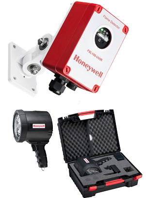
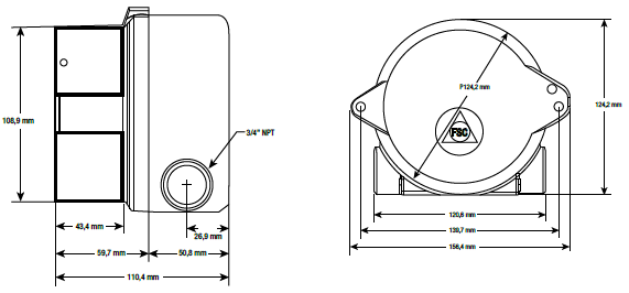
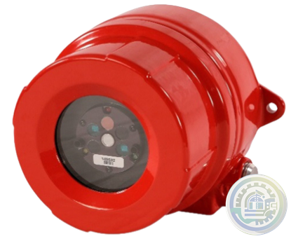
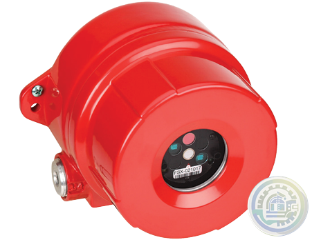
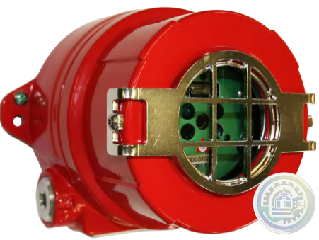
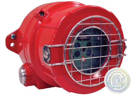
Honeywell Fixed Flame Detectors FSL100 Flame Detectors Features & Benefits
-
Honeywell Fixed Flame Detectors FSL100 Flame Detectors
-
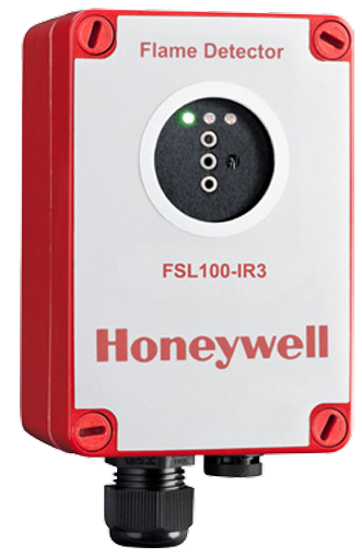
Honeywell FSL100 Series FSL100-IR3 Flame Detectors
-
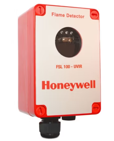
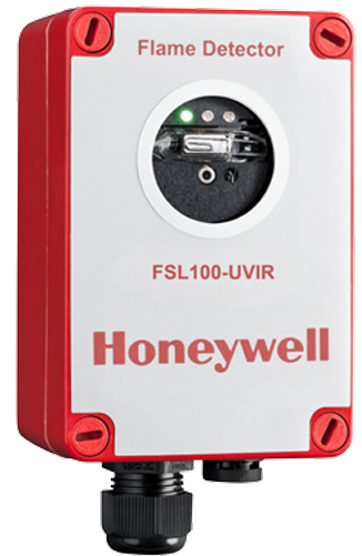
Honeywell FSL100 Series FSL100-UV/IR Flame Detectors
-
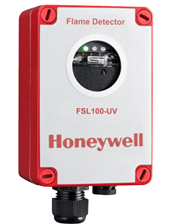
Honeywell FSL100 Series FSL100-UV Flame Detectors
-
Honeywell FSL100 Series Flame Detectors
-
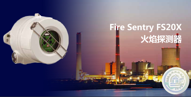
Honeywell Fire Sentry FS20X FireAnalytics Lines of Business
-
Honeywell Fire Sentry FS20X Fire and Flame Detector Conventional
-
Honeywell Fire Sentry FS20X Fire and Flame Detector Benefits
-
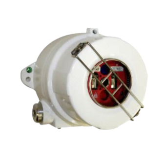
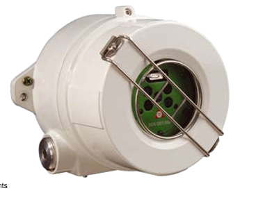
Honeywell Fire Sentry FS20X Fire and Flame Detector
-
Honeywell FS20X Fire and Flame Detector
-
Honeywell FS24X Detector FEATURES True triple IR wide band sensing and sophisticated detection algorithms
-
Honeywell FS24X Detector True triple IR wide band sensing and sophisticated detection algorithms
-
Honeywell FS20X Advanced Multi Spectrum (UV/Dual IR/VIS) Flame Detector FEATURES
-
Honeywell FS20X Advanced Multi Spectrum (UV/Dual IR/VIS) Flame Detector
-
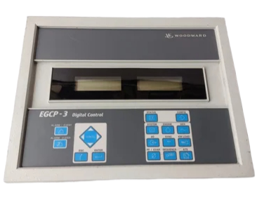
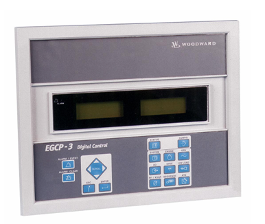
Woodward EGCP-3 Generator System Control Package HARDWARE SPECIFICATIONS
-
Woodward EGCP-3 Generator System Control Package Functions
-
Woodward EGCP-3 Generator System Control Package APPLICATIONS
-
Woodward EGCP‐3 LS and SPM‐D on the Yacht Sea Jewel Application
-
Woodward EGCP‐3 LS and SPM‐D on the Yacht Sea Jewel
-
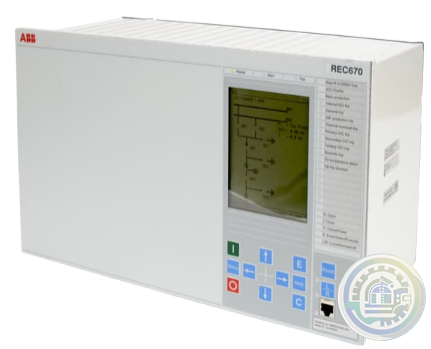
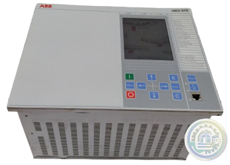
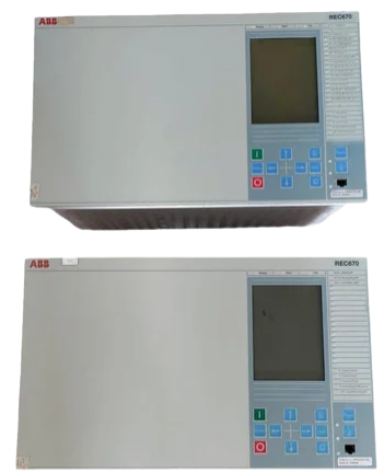
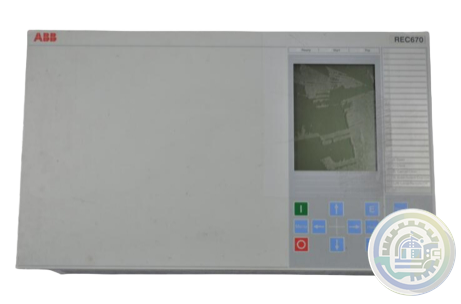
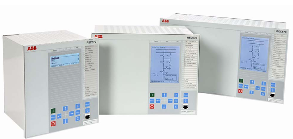
ABB REC 670 Bay control IED Functionality
-
ABB REC 670 Bay control IED Application
-
ABB REC 670 Bay control IED Functions 2
-
ABB REC 670 Bay control IED Functions
-
ABB REC 670 Bay control IED Features
-
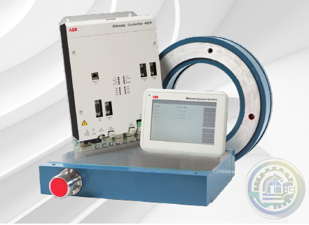
ABB Millmate Roll Force System Health check Service duration
-
ABB Millmate Roll Force System Health check Overview
-
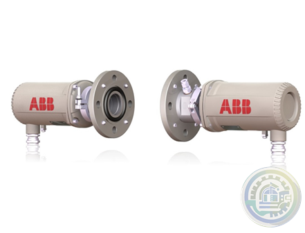
ABB LS4000 Tunable diode laser analyzer Certifications
-
ABB LS4000 Tunable diode laser analyzer Technical data
-
ABB LS4000 Tunable diode laser analyzer Introduction
-
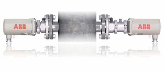
ABB LS4000 How it works – measuring principle
-
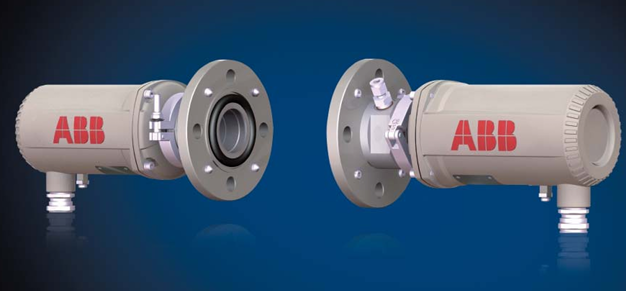
ABB LS4000 Tunable diode laser analyzer
-
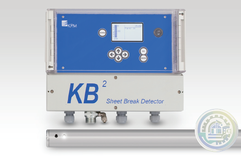
ABB KB² Fibre-Optic Sheet Break Detector Benefits
-
ABB KB² Fibre-Optic Sheet Break Detector
-
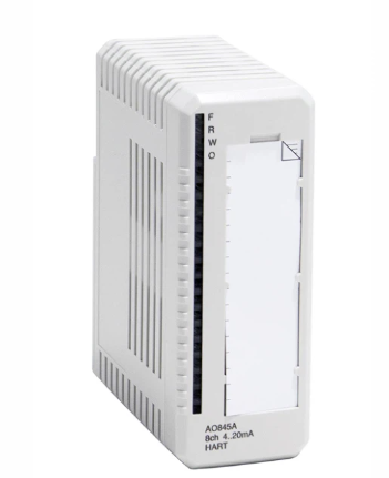
AO845A ABB Ability™ System 800xA® hardware selector
-
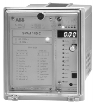
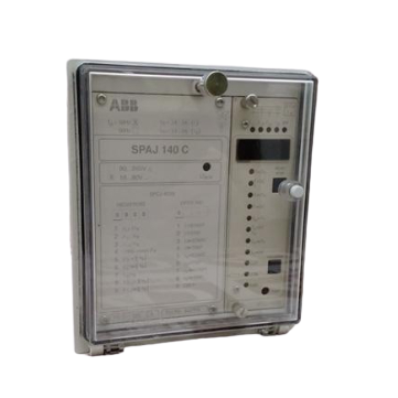
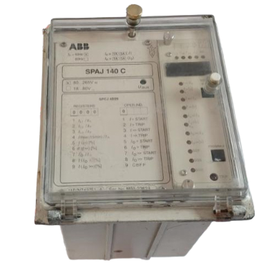
ABB SPAJ 140 C Combined overcurrent andearth-fault relay Features
-
ABB SPAJ 140 C Series A world-class relay collection for optimised protection functions
-
ABB SPAJ 140 C Series Combined Overcurrent and Earth-fault Relays
-
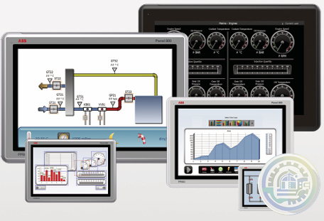
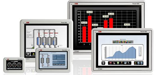
ABB PANEL 800 VERSION 6.2
-
ABB Compact Product Suite Panel 800 Version 6
-
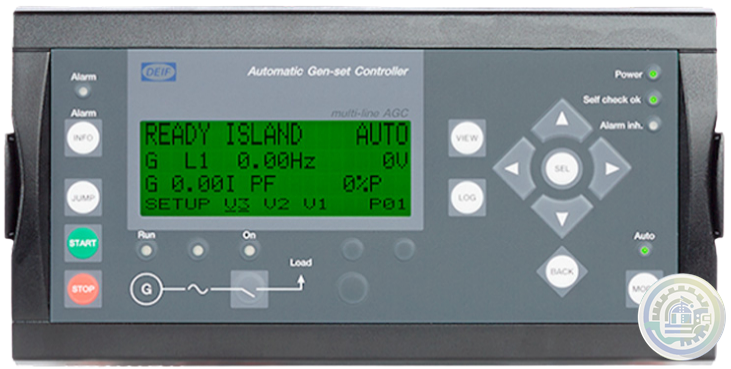
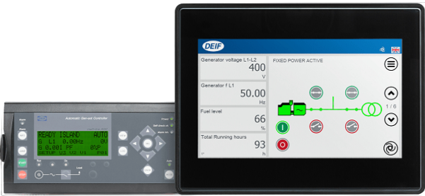
DEIF Automatic Genset Controller AGC-4 features
-
DEIF Automatic Genset Controller AGC-4
-
Emerson KJ4002X1-BE1 Top Extender Cable Assembly
-
Emerson PMCspan PMC Expansion Mezzanine Specifications
-
Emerson PMCspan PMC Expansion Mezzanine Details
-
Emerson PMCspan PMC Expansion Mezzanine
-
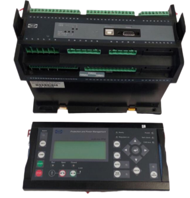
DEIF DU-2/MKIII Paralleling And Protection Unit 24VDC Applications
-
DEIF DU-2/MKIII Paralleling And Protection Unit 24VDC
-
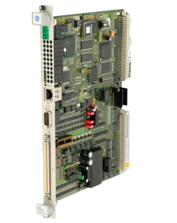
Alstom/General Electric controller with SPU232.2 029.366.817
-
Alstom/General Electric controller with ICP232 029.359325
-
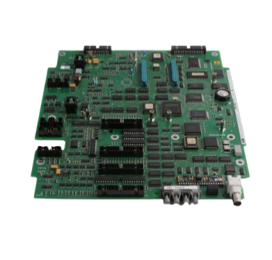
ABB excitation board card 3BHE014967R0002 UNS 2880B-P,V2
-
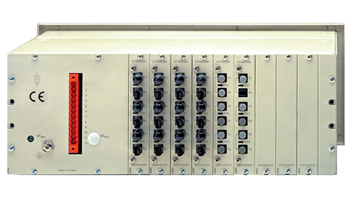
ABB Lon Star-Coupler RER 111
-
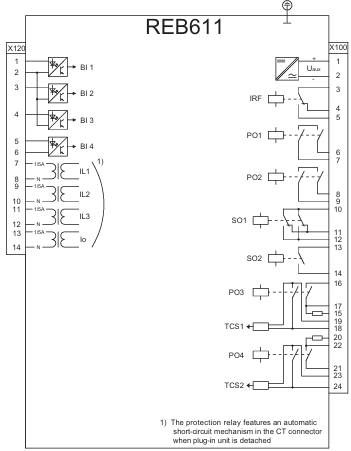
ABB REB611 Busbar and Multipurpose Differential Protection Tools
-
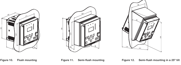
ABB REB611 Busbar and Multipurpose Differential Protection Mounting methods
-
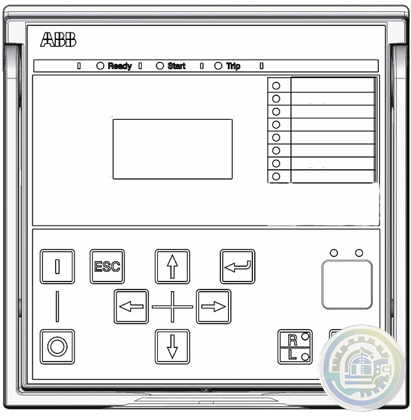
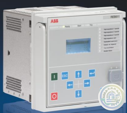
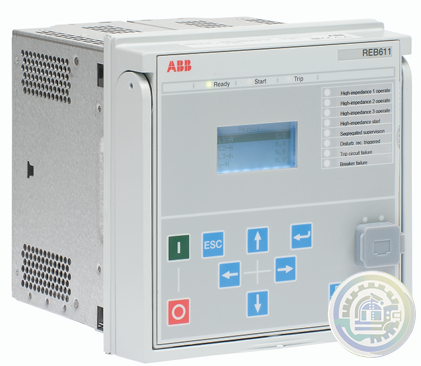
ABB REB611 Busbar and Multipurpose Differential Protection Local HMI
-
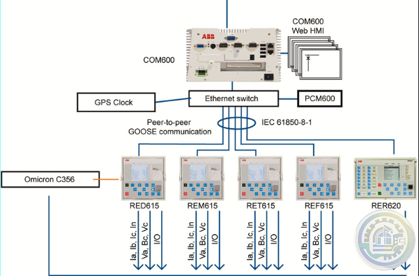
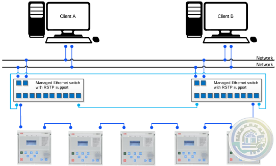
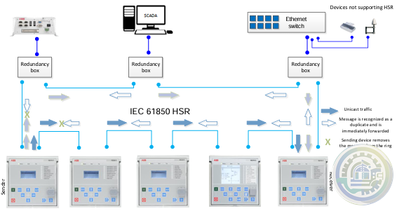
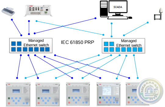
ABB REB611 Busbar and Multipurpose Differential Protection Station communication 2
-
ABB REB611 Busbar and Multipurpose Differential Protection Station communication
-
ABB REB611 Busbar and Multipurpose Differential Protection Access control
-
ABB REB611 Busbar and Multipurpose Differential Protection Recorded data
-
ABB REB611 Busbar and Multipurpose Differential Protection Control
-
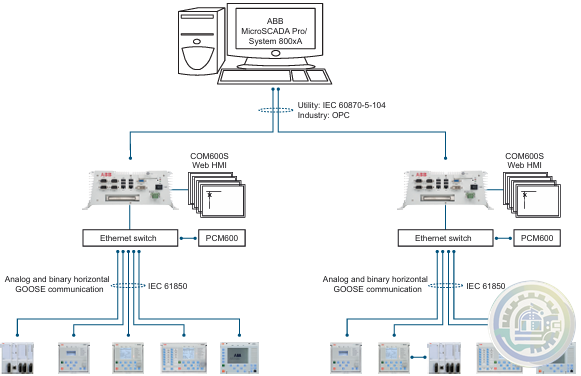
ABB REB611 Busbar and Multipurpose Differential Protection Supported ABB solutions
-
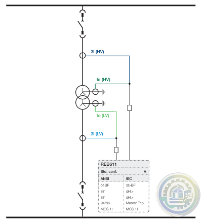
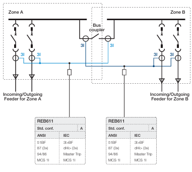
ABB REB611 Busbar and Multipurpose Differential Protection Application
-
ABB REB611 Busbar and Multipurpose Differential Protection functions
-
ABB REB611 Busbar and Multipurpose Differential Protection and Control
-
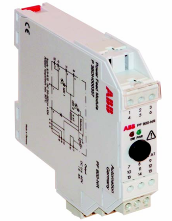
ABB PF 900-NR Power Feed Module
-
ABB HS 810 Head station for LD 800P
-
ABB CI532V02 Submodule MODBUS Interface, 2 channels
-
ABB CTI 21 - Temperature input module
-
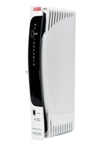
ABB RAO02 Redundant Analog Output module
-
ABB 086339-001 PWA, SENSOR MICRO-101
-
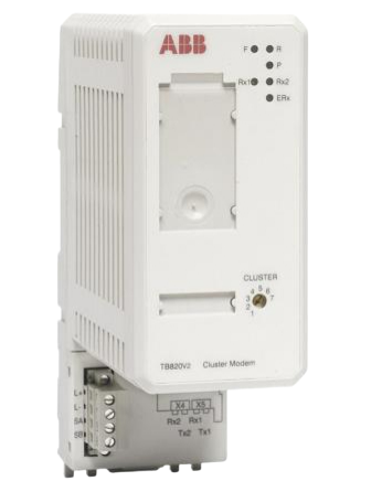
ABB 3BSE013208R1 TB820V2 Modulebus Cluster Modem
-
GE Mark VIe Wind IS215WEMAH1A Printed Circuit Board
-
ABB TU810V1 Compact Product Suite hardware selector
-
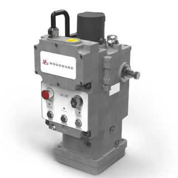
Woodward Digital Valve Positioner (DVP)
-
A-B Ethernet Media Cable Spools Shielded Twisted Pair (Foil & Braided Shield)
-
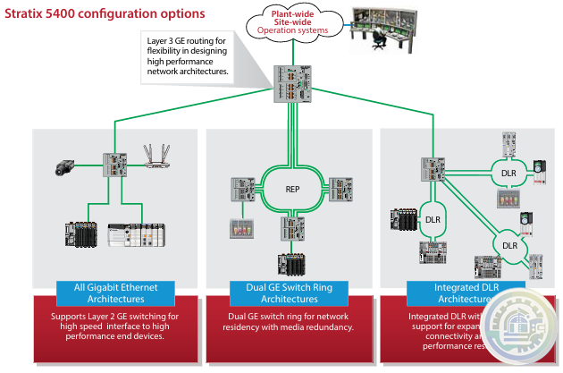
A-B Stratix 5400 Industrial Managed Switch Features and Benefits
-
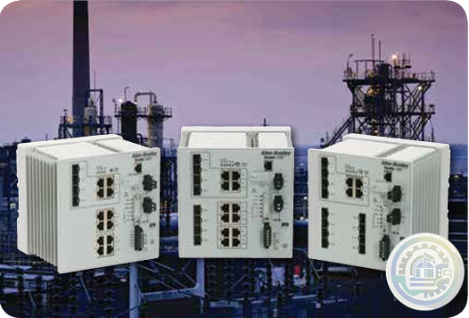
A-B Stratix 5400 Industrial Managed Switch
- Bristol Babcock
- Rolls-Royce
- Aerotech
- APPLIED MATERIALS
- Basler
- SAACKE
- BENDER
- Kollmorgen
- MEGGITT
- METSO
- MITSUBISHI
- MTL
- HIMA
- Siemens
- BACHMANN
- AMAT
- DEIF
- DELTATAU
- EATON
- ELAU
- LAM
- SCHNEIDER
- Advantest
- ABB
- GE
- Emerson
- Motorola
- A-B
- KUKA
- Abaco
- HITACHI
- SST
- Vibro-Meter
- Rexroth
- Prosoft
- DFI
- Scanlab
- Reliance
- Parker
- Woodward
- MOOG
- NI
- FOXBORO
- Triconex
- Bently
- ALSTOM
- YOKOGAWA
- B&R
- UNIOP
- KONGSBERG
- Honeywell
- Omron
- CTI
- EPRO
- Tell:+86-18144100983
- email:kongjiangauto@163.com
- Application:wind/ petroleum/ chemical/ natural gas/ Marine/ mining/ aviation/ electronics/ steel/ nuclear power/ electric power/ coking/ air separation and so on
- Series:PLC/ DCS/ servo/ analog/ Ethernet/ digital/ redundant module/ tension system/ excitation/ generator management/ human-machine interface/ detection card/ sensor/ AC drive/ etc
Hinweis zur Installation
Die Montageplatte (linke Endplatte) für das Netzteil verfügt über die in der
nachfolgenden Abbildung dargestellten Schrauben. Die mittlere und die rechte
Endplatte werden durch ein Gussform-Kupplungselement in Position gehalten,
sodass keine Schrauben erforderlich sind.

Connect Ground Bus to Grounding-Electrode System
The grounding-electrode system is at earth-ground potential and is the central ground for all electrical equipment and ac power within any facility.
Use a grounding-electrode conductor to connect the ground bus to the grounding-electrode system.
Use at minimum 8.3 mm2 (8 AWG) copper wire for the grounding-electrode conductor to guard against EMI.
The National Electrical Code specifies safety requirements for the grounding-electrode conductor.
Collegare il conduttore di messa a terra dell'apparecchiatura al bus diterra
Collegare il conduttore di messa a terra dell'apparecchiatura da ciascun chassis adun singolo bullone del bus di terra.
• Usare una treccia in rame da 2.54 cm o un filo in rame da 5.2 mm2 (10 AWG) per collegare i singoli
chassis, la custodia ed un bus di terra centrale montato sul pannello posteriore
• Usare una custodia in acciaio per evitare disturbi elettromagnetici (EMI)
• Assicurarsi che il visore posto sullo sportello della custodia sia uno schermo laminato o un substrato
ottico conduttivo (per bloccare gli EMI)
• Installare un cavo di massa per il contatto elettrico tra lo sportello e la custodia; non utilizzare la
cerniera a tal scopo
Install the Chassis Interconnect Cable (optional)
To connect up to three chassis together (for a maximum of 30 I/O slots), install the chassis interconnect cable before attaching your power supply.

Vis M4 ou M5 (n° 10 ou n° 12)
• des vis cruciformes et des rondelles éventail (ou vis SEM, vis cruciforme avec
rondelle éventail imperdable) pour les pattes de fixation du châssis ;
• un tournevis cruciforme ;
• une perceuse.
Documentation
La documentation sur :
• votre processeur ou adaptateur d’E/S ;
• votre bloc d’alimentation ;
• vos modules de communication et/ou modules d’E/S.

More Model Recommendations:
1756-OB16IS module Rockwell ControlLogix 16 digital output
1756-OB32 module Rockwell ControlLogix 32 digital output
1756-OB8 module Rockwell ControlLogix 8 digital output
1756-OB8EI module Rockwell ControlLogix 8 digital output
1756-OB8I module Rockwell ControlLogix 8 digital output
1756-OC8 module Rockwell ControlLogix 8 digital output
1756-PA75 Module Rockwell ControlLogix AC Power Supply
1756-PA75R Module Rockwell ControlLogix AC Power Supply
1756-PAR2 Module Rockwell ControlLogix AC Power Supply
1756-PAXT Module Rockwell ControlLogix XT Power Supply
1756-PB72 Module Rockwell ControlLogix DC Power Supply
1756-PB75 Module Rockwell ControlLogix DC Power Supply
1756-PB75R Module Rockwell ControlLogix DC Power Supply
1756-PBR2 Module Rockwell ControlLogix Power Supply
1756-PBXT Module Rockwell ControlLogix XT Power Supply
1756-PC75 Module Rockwell ControlLogix DC Power Supply
1756-PH75 Module Rockwell ControlLogix DC Power Supply
1756-PSCA2 Module Rockwell ControlLogix Adapter
1756-OF4 module Rockwell ControlLogix 4 analog
1756-OF6CI module Rockwell ControlLogix 6 analog
1756-OF6VI module Rockwell ControlLogix 6 analog
1756-OF8 module Rockwell ControlLogix 8 analog
1756-OF8H module Rockwell ControlLogix 8 analog
1756-OG16 module Rockwell ControlLogix 16 digital output
1756-OH8I module Rockwell ControlLogix 8 digital output
1756-ON8 module Rockwell ControlLogix 8 digital output
1756-OV16E module Rockwell ControlLogix 16 digital output
1756-OV32E module Rockwell ControlLogix 32 digital output
1756-OW16I module Rockwell ControlLogix 16 digital output
1756-OX8I module Rockwell ControlLogix 8 digital output
1756-PA72 Module Rockwell ControlLogix AC Power Supply
| User name | Member Level | Quantity | Specification | Purchase Date |
|---|


Please do not listen to the advice of non-professional engineers! Cause equipment damage!


wechat/whatsapp:
+86-181-4410-0983
Email: kongjiangauto@163.com
-
ABB UCD224A103 digital input/output module
-
ABB PDD205A0121 power distribution device
-
ABB PDD205A1121 power distribution device
-
ABB DSDX453 Digital input/output (DIO) expansion card
-
ABB DSPC454 Processor Board
Copyright © 2009 - 2024 Cld , All Rights Reserved K-JIANG All rights reserved


