-
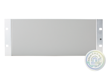
Emerson KJ4010X1-BX2 Blank Nameplate Insert (Quantity 10 in package)
-
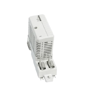
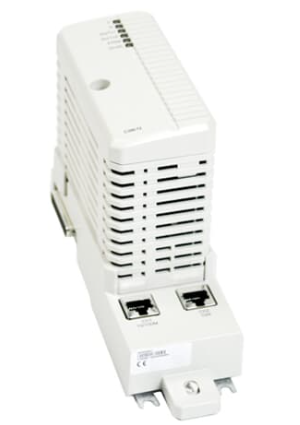
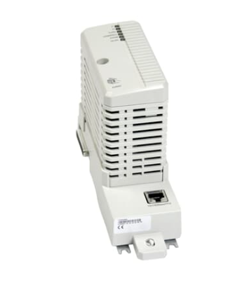
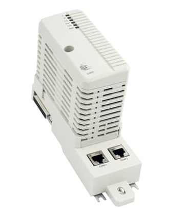
ABB AO2060-Caldos15,-Caldos17,-Magnos106,-Uras14Category 2G Analyzer Modules
-
ABB URAS 14 analyzer, AO2040, 768459 H NO
-
Emerson VE6050T04-ACC Transceiver module for Smart Switches
-
Emerson VE6050T04-AO Transceiver module for Smart Switches
-
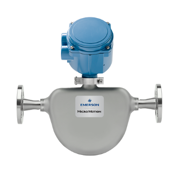
Emerson Micro Motion ELITE CMFS007M Coriolis Meter
-
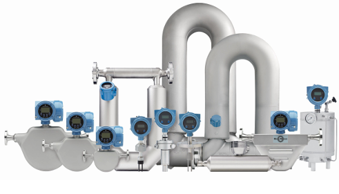
Emerson Micro Motion™ Technical Overvie
-
Emerson Mechanical Solutions and Services
-
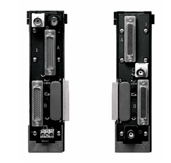
Emerson KJ4010X1-BG1 Right LocalBus Extender Cable Assembly
-
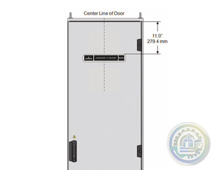
Emerson DeltaV™ Cabinet Nameplate
-
Emerson DeltaV™ M-series I/O carriers System Compatibility
-
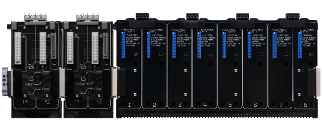
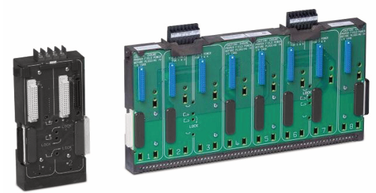
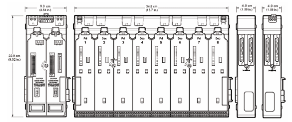
Emerson The DeltaV horizontal-mount 8-wide I/O interface carrier with individual field power per I/O card
-
Emerson DeltaV™ M-series I/O Subsystem Horizontal Carriers
-
ABB CI873A Ability™ System 800xA® hardware selector
-
ABB DIS880 Ability™ System 800xA® hardware selector
-
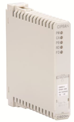
ABB CI920AN (CIPBA) Ability™ System 800xA® hardware selector
-
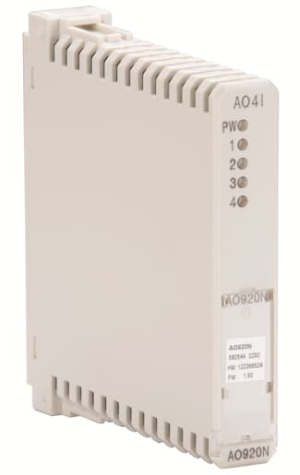
ABB AO920N (AO4I) Ability™ System 800xA® hardware selector
-
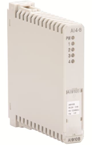
ABB AI910B (AI4-B) Compact Product Suite hardware selector
-
ABB AO2060 Category 2G Analyzer Modules
-
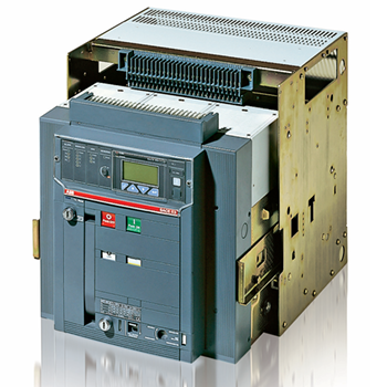
ABB Preventive maintenance for Emax low voltage air circuit breakers
-
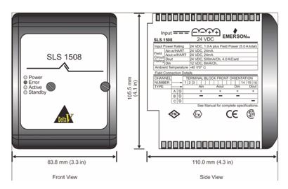
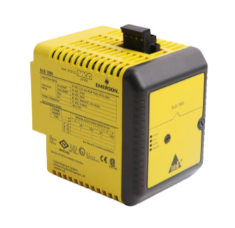
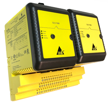
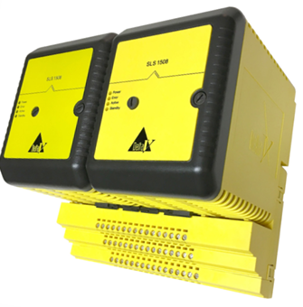
Emerson Redundancy SLS 1508 Logic Solver modules
-
Emerson Unique Redundancy Methodology
-
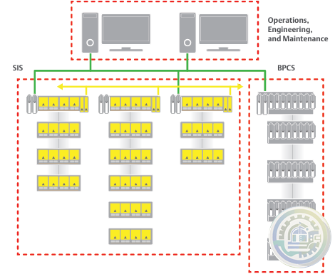
Emerson DeltaV SIS™ Logic Solver Communication
-
Emerson DeltaV SIS™ Logic Solver DeltaV SIS Hardware
-
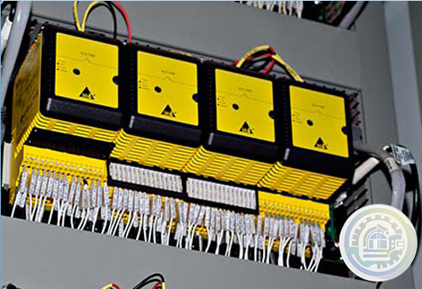
Emerson DeltaV SIS™ Logic Solver Benefits-Flexible deployment
-
Emerson DeltaV SIS™ Logic Solver
-
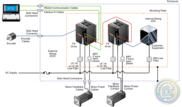
Emerson Typical CE Mark FX System Configuration
-
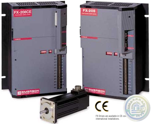
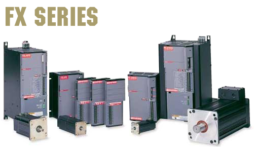
Emerson CE MARK FX SERIES POSITIONING SERVO DRIVE SYSTEMS
-
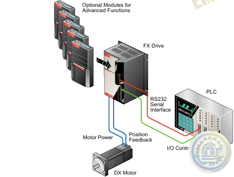
Emerson FX Series Positioning Servo Drive Systems Features
-
Emerson FX Series Positioning Servo Drive Systems
-
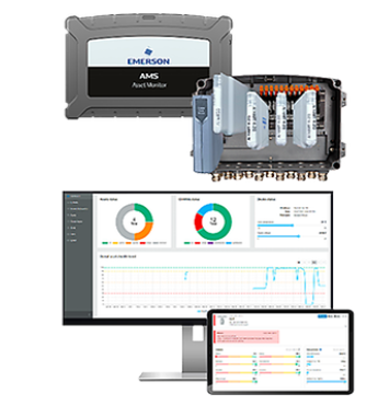
Emerson AMS Asset Monitor
-
Emerson Online Prediction, Protection and Process Monitor
-
Emerson The next step in your digital transformation just got easier!
-
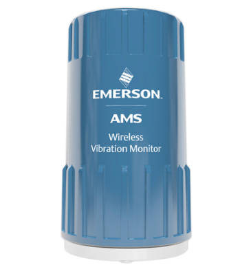
Emerson AMS Wireless Vibration Monitor
-
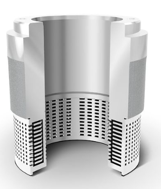
Emerson Fisher™ WhisperFlo™ Aerodynamic Noise Attenuation Trim
-
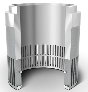
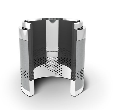
Emerson Fisher™ Whisper Trim™ I Cage
-
Emerson Fisher™ Whisper Trim™ III Cage
-
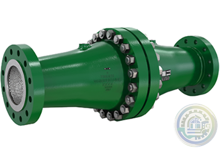
Emerson Fisher™ 6060 WhisperTube Modal Attenuator
-
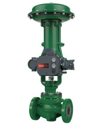
Emerson Fisher™ easy-e™ EA SERIES Control Valve
-
Emerson Rosemount 8700 Series Magnetic Flowmeter Systems
-
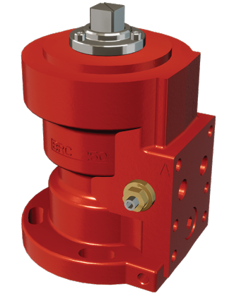
Emerson Damcos™ BRC 250 Hydraulic Double-acting Balanced Rotary Actuator 90° (Quarter-turn)
-
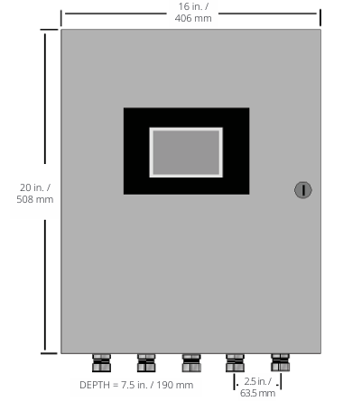
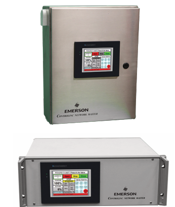
Emerson Model M250N Mounting of Rack Mount Enclosure
-
Emerson Model M250N Controlinc Network Controller System Configuration
-
Emerson Controlinc Network Master Model M250 Version 5.2
-
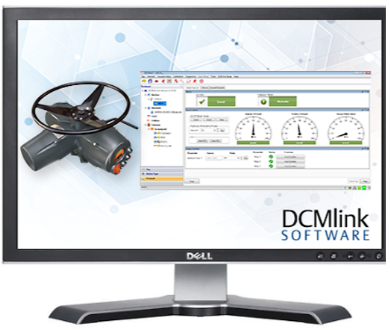
Emerson DCMlink Software
-
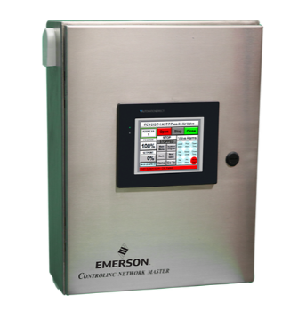
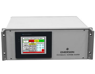
Emerson M250 Controlinc Network Master
-
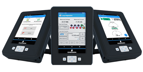
Emerson AMS Trex Device Communicator
-
Emerson AMS Trex™ Device Communicator with embedded Bluetooth® connectivity
-
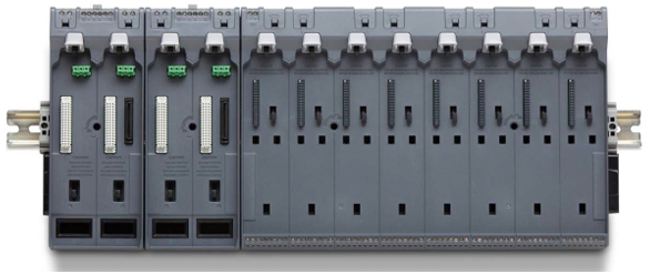
Emerson S-series Horizontal Carriers Product Description
-
Emerson S-series Horizontal Carriers Modular design allows flexible installation
-
Emerson S-series Horizontal Carriers
-
DEIF TAS-331DG AC transducer for active or reactive power
-
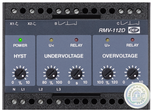
DEIF RMV-112D Undervoltage and overvoltage relay, U< and U>
-
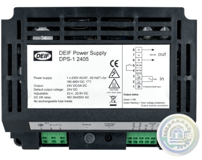
DEIF DPS-1 DC Power Supply
-
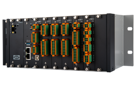
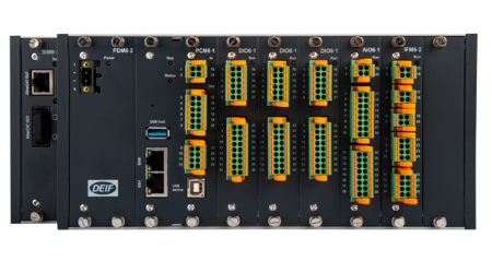
DEIF DM 400 hydro Integrated systems
-
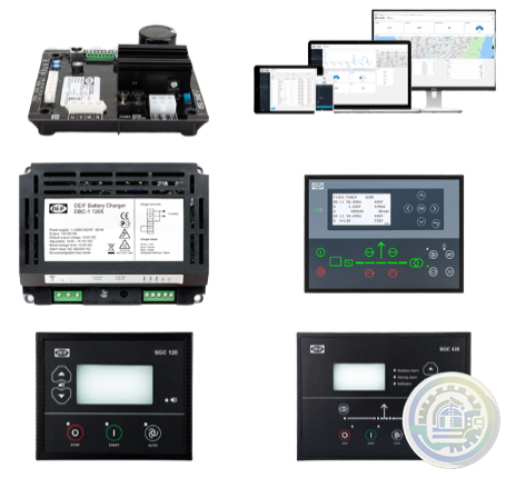
DEIF DBC-1 Battery charger
-
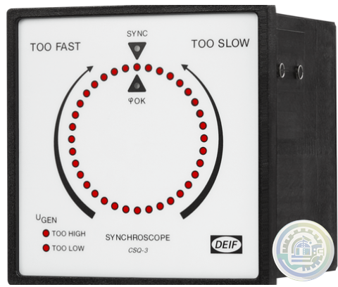
DEIF CSQ-3 Multi-function synchroscope
-
DEIF CODESYS Programming editor and debug
-
DEIF CODESYS Features Software - AWC 500 development package
-
DEIF AMC 300 Features Advanced Programmable Controller
-
DEIF AMC 300 Performance and system design freedom
-
DEIF AMC 300 Flexible solution design options
-
DEIF AMC 300 Advanced Programmable Controller
-
DEIF AGI 400 Features Advanced graphical interface
-
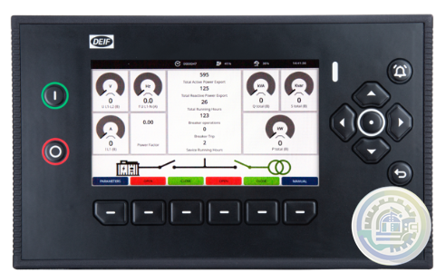
DEIF AGI 400 Advanced graphical interface
-
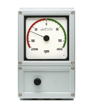
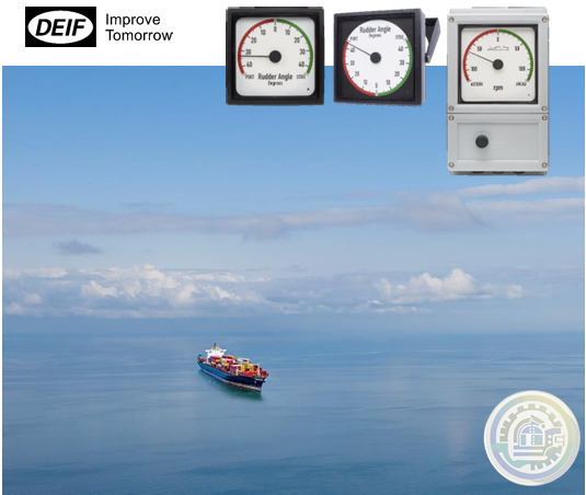
DEIF BRW-2 & BW Analogue illuminated bridge wing indicators
-
DEIF Basic control package for mobile generators
-
DEIF AWC 500 - G59/3 Integrated G59/3 protection turbine controller unit
-
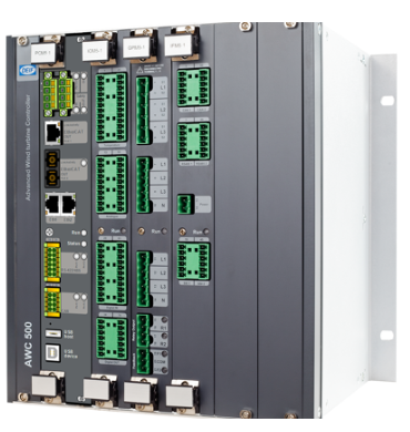
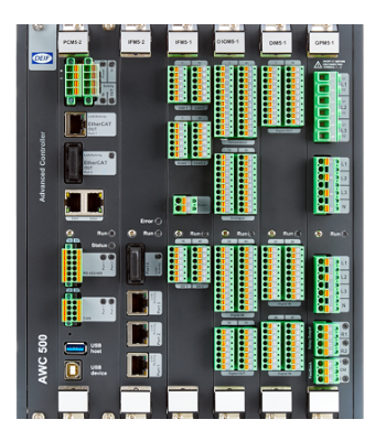
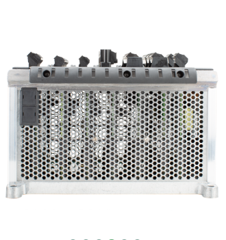
DEIF AWC 500 Advanced Controller
-
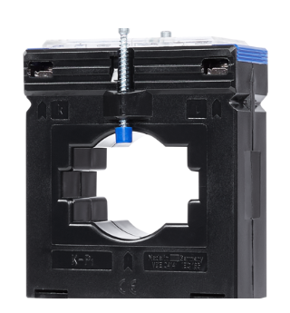
DEIF ASK & ASR Measuring transformer
-
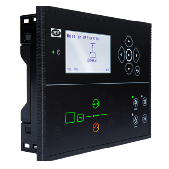
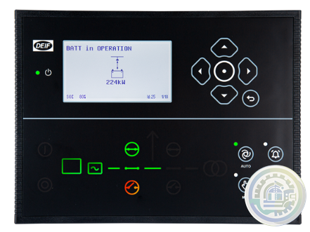
DEIF ASC-4 Battery Energy source, power source, or droop mode
-
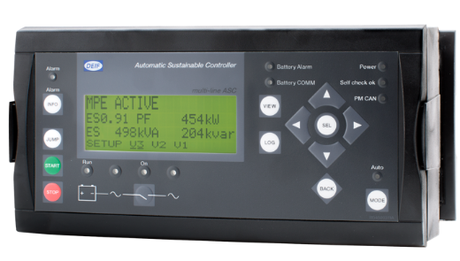
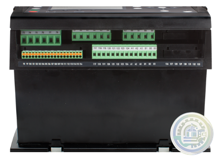
DEIF ASC-4 Battery Automatic Sustainable Controller
-
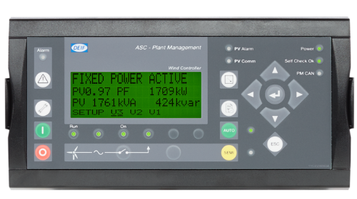
DEIF ASC plant management Ideal for self-consumption applications
-
DEIF ASC plant management Automatic sustainable controller
-
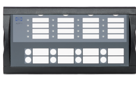
DEIF AOP Additional operator panel
-
DEIF AMC 600 Fast, fail-safe, and secure system software
-
DEIF AMC 600 Wide range of protocols supported
-
DEIF AMC 600 Programmable automation controller with EtherCAT based I/O
-
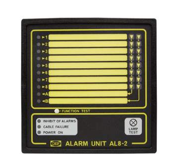
DEIF AL8-2 Alarm panel
-
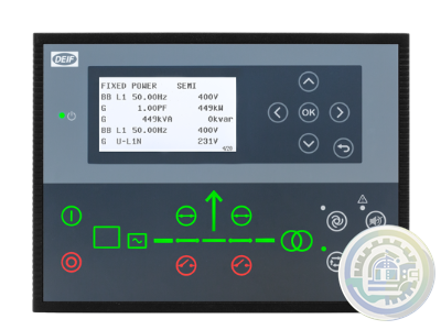
DEIF AGC 150 Hybrid Advanced Genset Controller
-
DEIF AGC 150 PMS Lite Simple power management controller
-
DEIF AGC 150 Generator Advanced Genset Controller
-
DEIF AGC 150 Remote Display Remote access and control unit
-
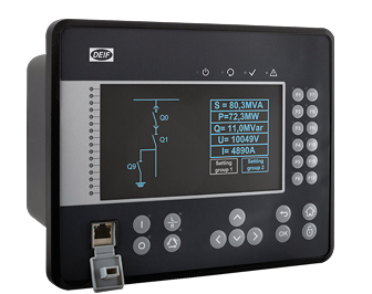
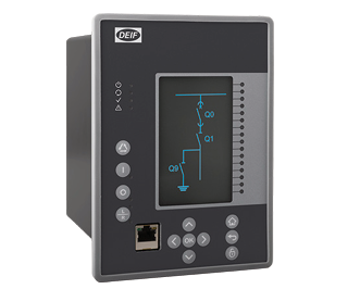
DEIF MVR-250 series Medium Voltage Relay
-
DEIF MVR-210 series Medium Voltage Relay
-
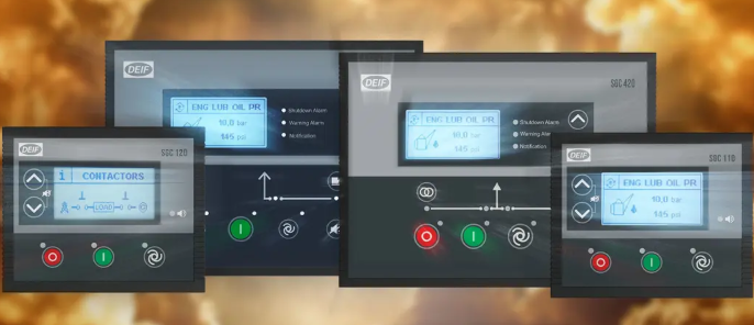
DEIF The SGC series
-
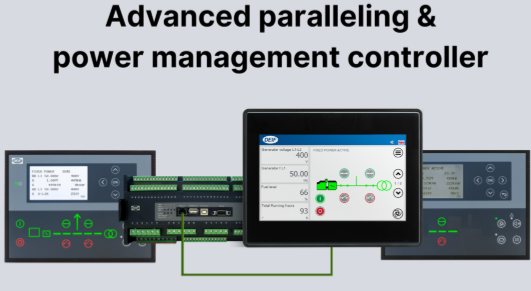
DEIF Advanced paralleling and power management controllers
-
DEIF Engine and single genset controllers
-
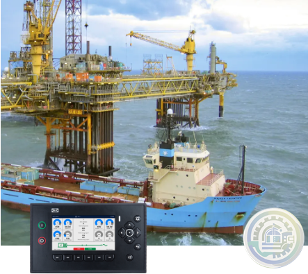
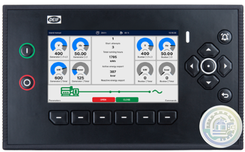
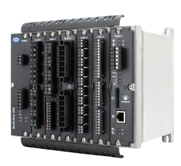
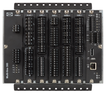
DEIF iE 350 Marine Highly flexible and cybersecure intelligent energy controller
-
DEIF iE 250 Marine Versatile and cybersecure intelligent energy controller for maritime applications
-
DEIF iE 150 Marine Simple and effective power management
-
DEIF iE 150 Marine Cost-effective and flexible controller for coastal, harbour, and inland vessels
-
DEIF iE 650 PLC Fast, fail-safe, and secure system software
-
DEIF iE 650 PLC Performance and flexibility with module concept
-
DEIF iE 650 PLC Extreme robust Programmable Automation controller with EtherCAT based I/O
-
DEIF iE 350 PLC Performance and system design freedom
-
DEIF iE 350 PLC Robust right out of the box
-
DEIF Advanced Features of the iE 350 PLC Controller
-
DEIF iE 250 PLC Versatile and modular intelligent energy PLC controller
-
DEIF XL / BW / BRW-2 Illuminated indicators
-
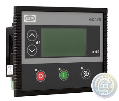
DEIF SGC 120/121 Single Genset Controllers
-
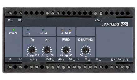
DEIF Load Sharing Unit LSU-112DG
-
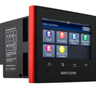
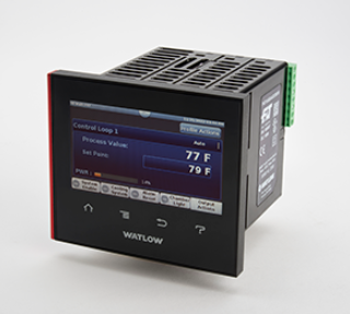
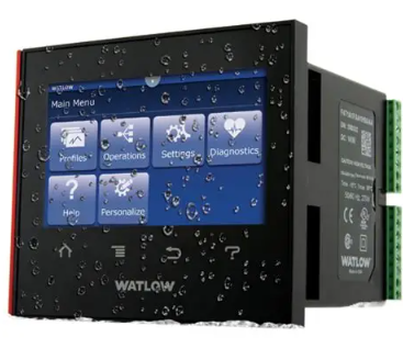
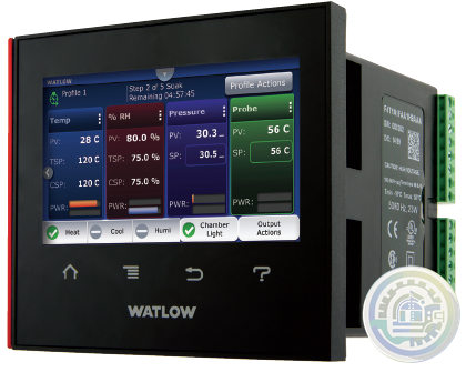
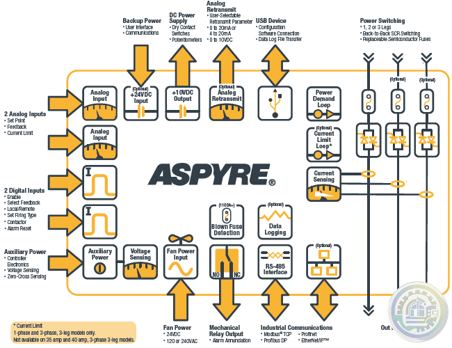
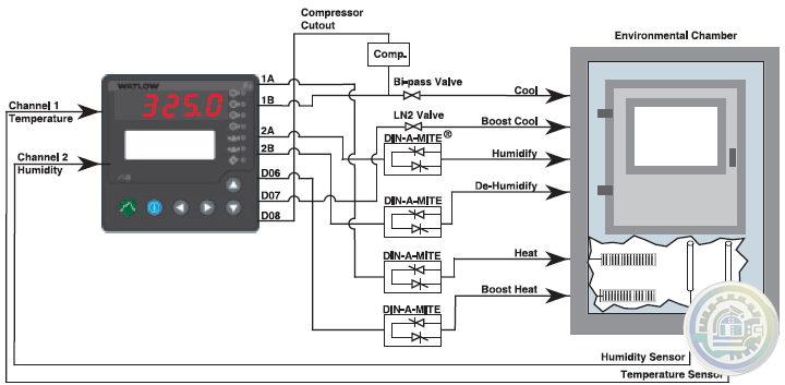
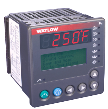
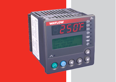
Watlow F4T Base Specifications
-
Watlow F4T Key Features and Options 1/4 DIN Process Controller
-
Watlow F4T 1/4 DIN Process Controller Features and Benefits
- Studer
- Watlow
- AEG
- ADVANCED
- KEBA
- Bristol Babcock
- Rolls-Royce
- Aerotech
- APPLIED MATERIALS
- Basler
- SAACKE
- BENDER
- Kollmorgen
- MEGGITT
- METSO
- MITSUBISHI
- MTL
- HIMA
- Siemens
- BACHMANN
- AMAT
- DEIF
- DELTATAU
- EATON
- ELAU
- LAM
- SCHNEIDER
- Advantest
- ABB
- GE
- Emerson
- Motorola
- A-B
- KUKA
- Abaco
- HITACHI
- SST
- Vibro-Meter
- Rexroth
- Prosoft
- DFI
- Scanlab
- Reliance
- Parker
- Woodward
- MOOG
- NI
- FOXBORO
- Triconex
- Bently
- ALSTOM
- YOKOGAWA
- B&R
- UNIOP
- KONGSBERG
- Honeywell
- Omron
- CTI
- EPRO
An important consideration for module placement is electromagnetic interference (EMI) from other equipment in the enclosure.
For example, VFs and AC servo drives generate high levels of EMI.
be sure to check other equipment for EMC compliance before placing it near the G123-814.
The rail release clip of the G122-829A001 should face down,
so the front panel and terminal identifications are readable and so the internal electronics receive a cooling airflow.
These Application Notes are a guide to applying the G122-829A001 P-I Servoamplifier.
These Application Notes can be used to:
Determine the closed loop structure for your application.
Select the G122-829A001 for your application. Refer also to data sheet G122-829.
Use these Application Notes to determine your system configuration.
Draw your wiring diagram.
Install and commission your system.GE Fanuc/ VMIC VMIVME-5532S VMEBus Fiber-Optic Repeater Link

In 914-EX cards with FPGA Firmware 0xB0 or greater, the “Remote Ethernet Link Speed Synchronization” (RLSS)
feature is enabled by default and can be disabled via the GUI. This feature forces the console side 914-EX to match
the speed and duplex settings of the remote side 914-EX. This greatly simplifies the setup and ensures the 914-EX
card adapts to the remotely plugged equipment for lossless communication. This setting is recommended and
should only be disabled if the configuration has another method to ensure link speed symmetry.
When configured for single expansion mode (default), the 914-EX combines the traffic from both Ethernet ports,
along with diagnostic information, onto a single medium speed expansion channel on the 914-HDE. This bandwidth
is dynamically shared between the two Ethernet ports, allowing for total throughput of up to 1000 Mb/s.
Optionally, the 914-EX can be configured for dual expansion mode, which uses two medium speed expansion
channels on the 914-HDE. This mode allows for a full 1000 Mb/s of bandwidth per Ethernet port and is ideal for
high bandwidth video over IP or GigE vision applications. Since the 914-HDE motherboard multiplexes the Ethernet
data from the 914-EX card and other expansion cards in the system, the total system bandwidth usage must be
considered, and be at (or under) the maximum optical bandwidth available for the system. Refer to Section 3.2 for
detailed information 914-X series card bandwidth usage.
Installation consists of mounting a horizontal DIN rail to the vertical rear surface of an industrial steel enclosure.
The rail release clips on the G123-814 should face downward to allow front panel and terminal
markings to be clearly readable and to allow cooling airflow to the internal electronics.
| FANUC VMIVME-7487 / VMIVME7487 |
| VMIC 333-657755-000 B LSC-3 4201 332-657755-000 E 332657755000 Board |
| INTERFACE VMIC VMIVME MODELE 5530S |
| VMIC 332-000132-B PCB 125848 |
| VMIC VMIATX 5553 |
| FANUC VMIVME-7452-53 5 / VMIVME7452535 |
| VMIC VMI VME 2330 Circuit Board VMIVME2330 |
| VMIC 7487A CPU BOARD 332-107487 H VMIVME PN 70512526000 |
| VMIC VMIVME 4116 VME 8-Channel 16-Bit Analog Output Board |
| VMIC / VMIPCI-5565-11 0000 / VMIPCI 5565 332-855565-110 000 U Cut 1pcs |
| 28307 VMIC PCB VMIVME MODEL 4512 332-004512-300 |
| Compact PCI VMIC VMIACC 0577 332-800577-000 A 332800577000A LSC-3 5003 Board |
| VMIC VMIOMAX-9102A POWER SUPPLY |
| VMIC VMIVME 7452 332-037452-645 C PCB BOARD X1PC |
| User name | Member Level | Quantity | Specification | Purchase Date |
|---|


Please do not listen to the advice of non-professional engineers! Cause equipment damage!


wechat/whatsapp:
+86-181-4410-0983
Email: kongjiangauto@163.com
-
ABB AO2060-Caldos15,-Caldos17,-Magnos106,-Uras14Category 2G Analyzer Modules
-
ABB URAS 14 analyzer, AO2040, 768459 H NO
-
ALSTOM VCM 232.2 ,029.359 088 ,VME-MANAGER-MASTER ,E0085.022.99
-
ALSTOM SPU232.1-CAN PART NO: 029.354 630. pecific model Large inventory
-
ABB 5C4045L0006 3MB030310R00001 3BH039203R0101 GVC736SE101 IGCT Module
Copyright © 2009 - 2024 Cld , All Rights Reserved K-JIANG All rights reserved


