-
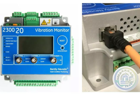
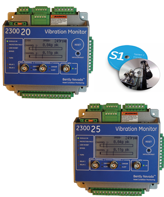
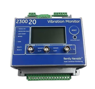
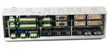
Bently Nevada 2300/20-CN Monitor with 4-20ma Outputs
-
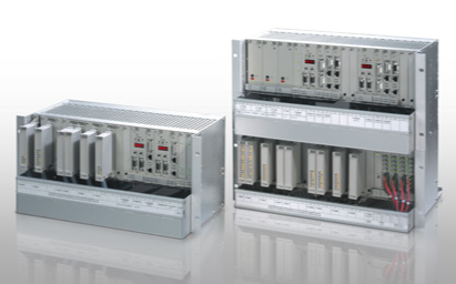
Bently Nevada 2300/20-RU 2300 Vibration Monitor
-
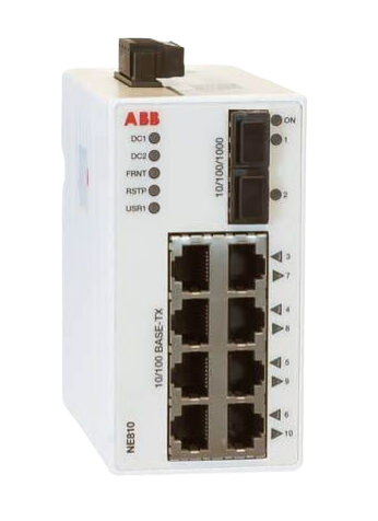
ABB NE810 3BSE080207R1 Network switch
-
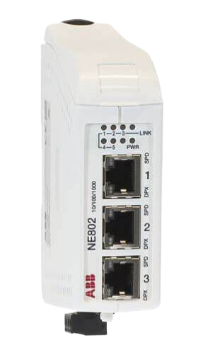
ABB NE802 Network switch 3BSE080237R1
-
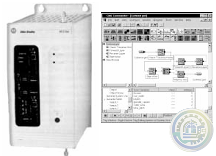
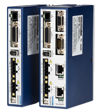
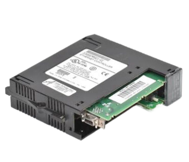
A-B 4100-234-R Compact Motion Controller
-
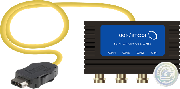
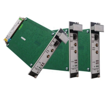
Bently Nevada ORBIT 60 SERIES Dynamic Input Modules Connectors
-
Bently Nevada ORBIT 60 SERIES Dynamic Input Modules Description
-
Bently Nevada Orbit 60 Series Robust cybersecurity
-
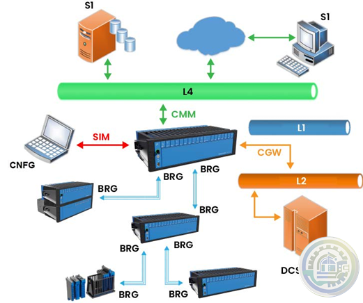
Bently Nevada ORBIT 60 SERIES System Overview
-
Bently Nevada ORBIT 60 SERIES System Overview Datasheet
-
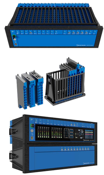
Bently Nevada ORBIT 60 SERIES
-
Bently Nevada 2300 Vibration Monitor Series Benefits
-
Bently Nevada 2300 Vibration Monitor Series Key Features
-
Bently Nevada 2300 Vibration Monitor Series Description
-
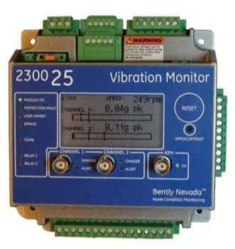
Bently 2300/25 2300 Vibration Monitor Key Features
-
Bently 2300/20 and 2300/25 2300 Vibration Monitors Features
-
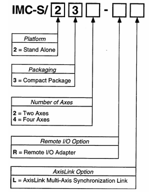
A-B IMC™ S Class Compact Motion Controllers Model Number Explanation
-
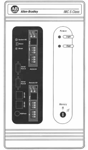
A-B IMC™ S Class Compact Motion Controllers (IMC-S/23x Models) Product Features
-
A-B IMC™ S Class Compact Motion Controllers (IMC-S/23x Models)
-
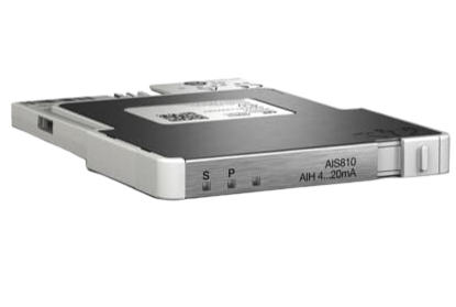
AIS810 ABB Ability™ System 800xA® hardware selector
-
NE810 ABB Ability™ System 800xA® hardware selector
-
ABB NE802 System 800xA hardware selector
-
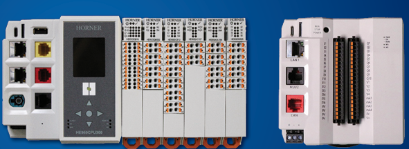
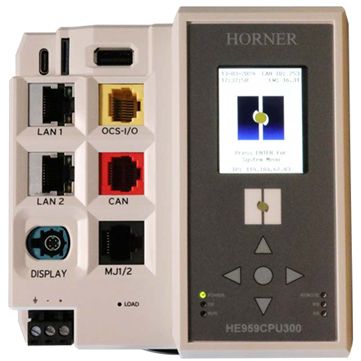
Horner OCS CPU Highly Expandable & Flexible Controller Solutions with OCS I/O Expansion
-
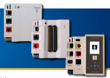
Horner CPU300 and HMI Connect Series Mounting Overview
-
Horner CPU300 and HMI Connect Series Features
-
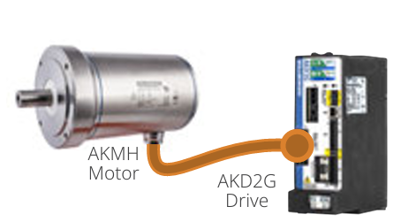
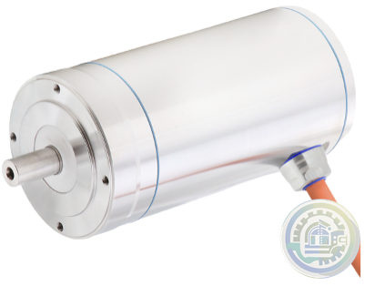
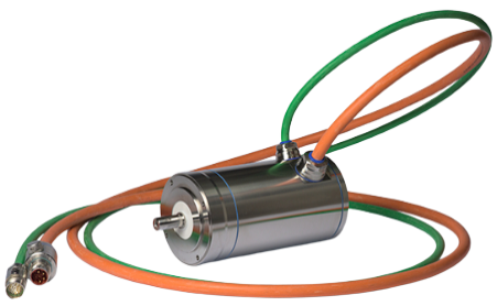
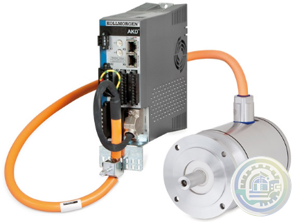
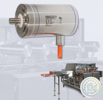
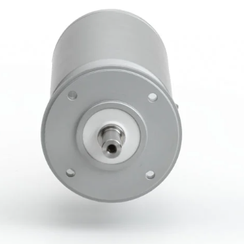
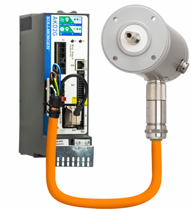
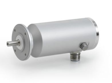
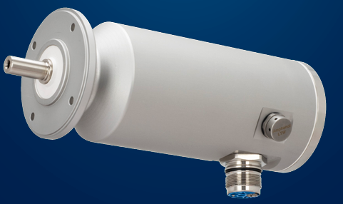
Kollmorgen AKMH™ Stainless Steel Washdown Motor Engineering Excellence
-
Kollmorgen AKMH™ Co-Engineered Solutions
-
Kollmorgen AKMH™ Stainless Steel Washdown Motor Modified Standard
-
Kollmorgen AKMH™ Stainless Steel Washdown Motor Brake Option
-
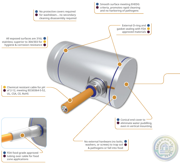
Kollmorgen AKMH™ Stainless Steel Washdown Motor Hygienic Design
-
Kollmorgen AKMH™ Stainless Steel Washdown Motor Protection Class
-
Kollmorgen AKMH™ Stainless Steel Washdown Motor Technical Guide
-
Kollmorgen AKMH™ Stainless Steel Washdown Motor Design Features
-
Kollmorgen AKMH™ Stainless Steel Washdown Motor Benefits Highly configurable
-
Kollmorgen AKMH™ Stainless Steel Washdown Motor Benefits
-
Kollmorgen AKMH™ Stainless Steel Washdown Motor Global Footprint
-
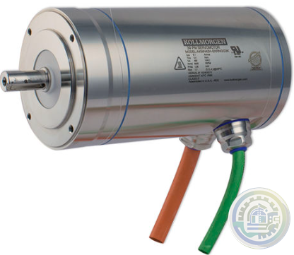
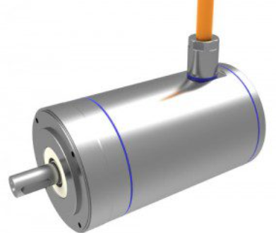
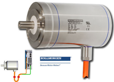
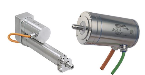
Kollmorgen AKMH™ Stainless Steel Washdown Motor
-
Kollmorgen AKMA™ Co-Engineered Solutions
-
Kollmorgen AKMA™ Universal Drive Solutions for Food,Beverage, and Pharmaceutical Industries
-
Kollmorgen AKMA™ Anodized Washdown Motor Features
-
Kollmorgen AKMA™ Anodized Washdown Motor Benefits
-
Kollmorgen AKMA™ Removing the Barriers of Design, Sourcing, and Time
-
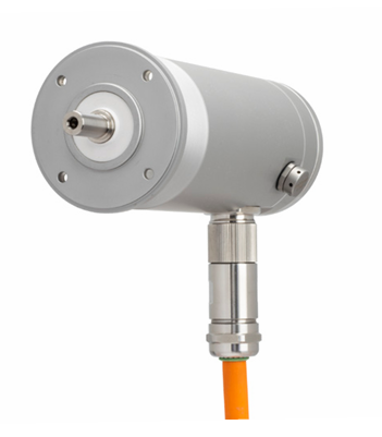
Kollmorgen AKMA™ Anodized Washdown Motor
-
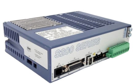
Kollmorgen S200 High Performance Compact Brushless Servo Drives Industry-leading
-
Kollmorgen S200 High Performance Compact Brushless Servo Drives Benefits
-
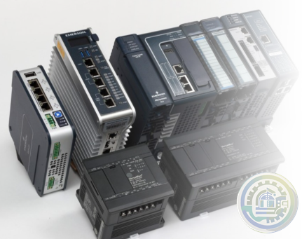
Emerson 00813-0100-0112 VersaMax Modular Input/Outputs and Controls Ease of Use
-
Emerson 00813-0100-0161 Compact Programmable Automation Controller Open communication
-
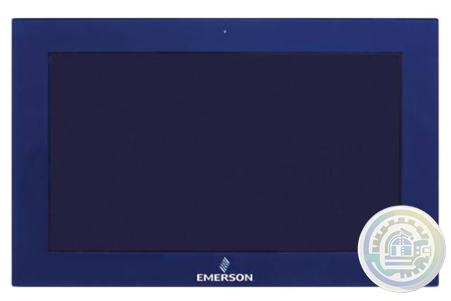
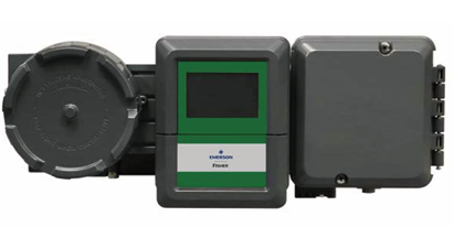
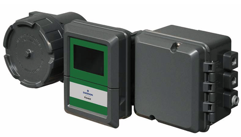
Emerson 00813-0100-0115 RXi - Industrial Monitor Designed for Visualisation
-
HIMA X-CPU 01 Processor Module Function
-
HIMA launches the fourth generation of its central module HIQuad X benefits
-
KEBA KeControl C5 - FE 560 Multi-protocol fieldbus expansion card
-
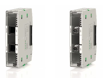
KEBA KeControl C5 - FE 571, FE 573 EtherCAT master expansion card
-
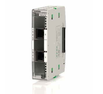
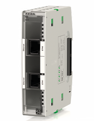
KEBA KeControl C5 - NE 551 Gbit Ethernet expansion card
-
KEBA KeDrive D3 controls – D3-DU 3x5 Control modules with built-in safety control
-
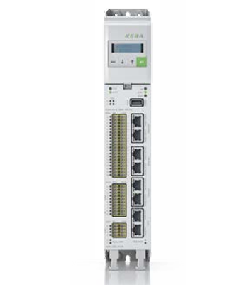
KEBA KeDrive D3 controls - D3-DU 3x0 Control modules
-
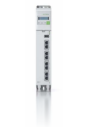
KEBA KeControl C1 Control modules
-
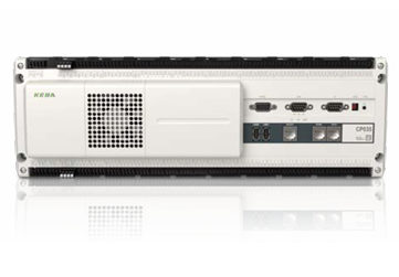
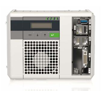
KEBA KeControl C5 - CP 5x0 Control modules
-
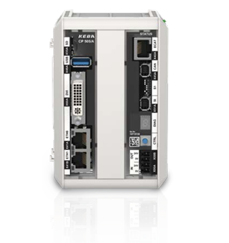
KEBA KeControl C5 - CP 50x Controls / Control units
-
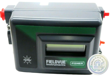
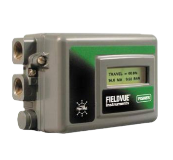
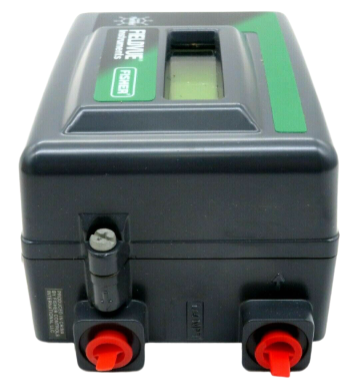
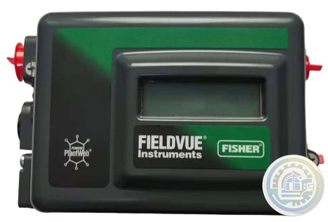
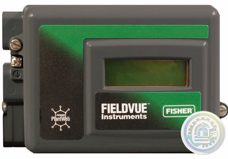
Emerson Fisher™ FIELDVUE™ DPC2K Digital Process Controller Performance
-
Emerson Fisher™ FIELDVUE™ DPC2K Digital Process Controller Value
-
Emerson Fisher™ FIELDVUE™ DPC2K Digital Process Controller Features
-
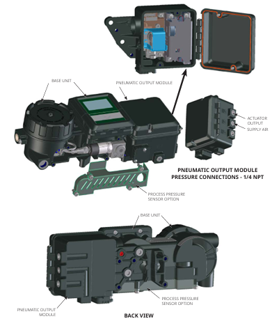
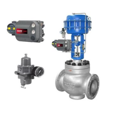
Emerson Fisher™ FIELDVUE™ DPC2K Digital Process Controller
-
Emerson Fisher™ FIELDVUE™ DVC6200p Digital Valve Controller Device Alerts
-
Emerson Fisher™ FIELDVUE™ DVC6200p Digital Valve Controller Value
-
Emerson Fisher™ FIELDVUE™ DVC6200p Digital Valve Controller Features
-
Emerson Fisher DVC6200 Digital Valve Controller Features
-
Emerson Fisher DVC6200 Digital Valve Controller Specifications
-
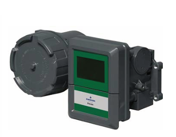
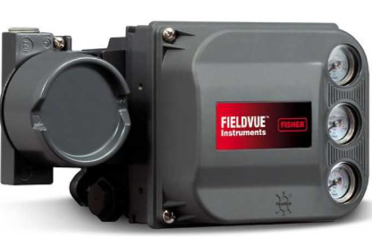
Emerson Fisher DVC6200 Digital Valve Controller
-
Emerson Fisher™ FIELDVUE™ DVC2000 Digital Valve Controller Instrument Shutdown
-
Emerson Fisher™ FIELDVUE™ DVC2000 Digital Valve Controller General Information
-
Emerson Fisher™ FIELDVUE™ DVC2000 Digital Valve Controller Restart Control Mode
-
Emerson Fisher™ FIELDVUE™ DVC2000 Digital Valve Controller Detailed Setup
-
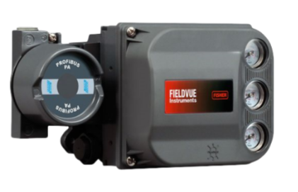
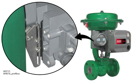
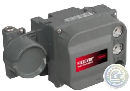
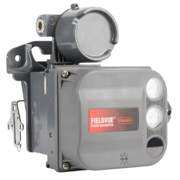
Emerson Fisher™ FIELDVUE™ DVC2000 Digital Valve Controller
-
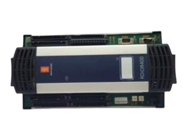
Kongsberg RDIO400 Remote Digital Inputs and Outputs Technical Specifications
-
Emerson CSI A6120 Enclosure Seismic Vibration Monitor Features
-
Kongsberg RL542A Radio Link Features
-
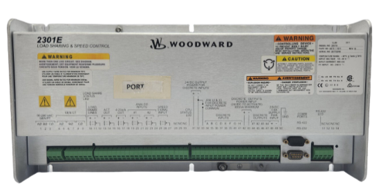
Woodward 2301E Digital Load Sharing and Speed Controller four modes of operation
-
ABB AC 800PEC High Performance Control System Modular structure
-
ABB AC 800PEC High Performance Control System Aluminium applications
-
GE IC693CMM321 Ethernet Interface Module Board Indicators
-
ABB Preventive maintenance for AF1350 ... AF2650 contactors Benefits
-
ABB DC switching contactors, type GAF A compact contactor up to 1000 V DC Features
-
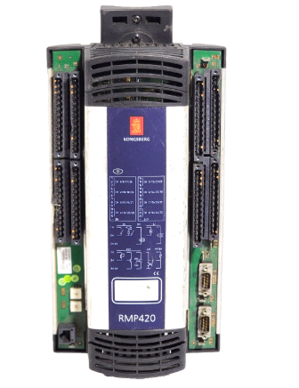
Kongsberg RMP420-Remote Multipurpose Input/Output
-
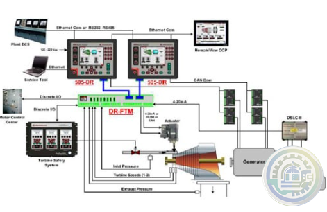
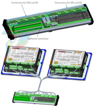
Woodward 505DR Dual Redundant Turbine Controller Control specifications
-
Woodward 505DR Dual Redundant Turbine Controller Communication
-
Woodward 505DR Dual Redundant Turbine Controller Description
-
Emerson M-Series DC to DC System Power Supplies Product Description
-
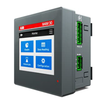
ABB M4M Network Analyser Transmission method
-
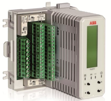
ABB FAU 810 Flame Analyser Unit Remote Monitoring
-
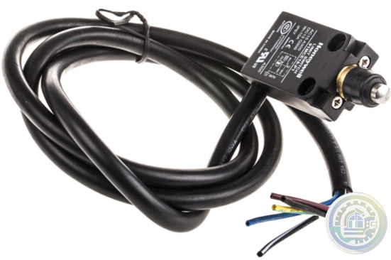
Honeywell 91MCE Series MICRO SWITCH Miniature Compact Limit Switches Features
-
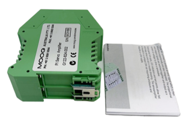
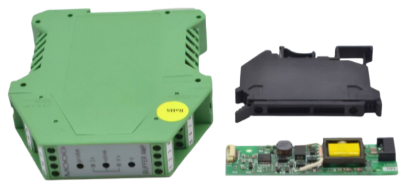
MOOG Dual PWM Amplifier G123-814 Wiring
-
MOOG Dual PWM Amplifier G123-814 Applying this amplifier
-
Emerson A6410 Dual Channel Valve and Enclosure Expansion Monitor Features
-
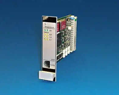
Emerson A6630 Temperature Monitor Machine Monitoring System sensor types
-
Parker C3S063V2F12I31T11M00 Compax3S Single Axis Servo Drive main application scenarios
-
Parker C3S063V2F12I31T11M00 Compax3S Single Axis Servo Drive applications
-
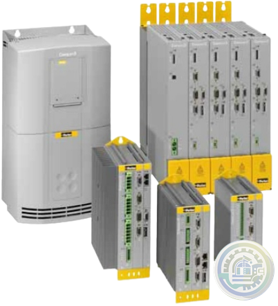
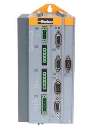
Parker C3S063V2F12I31T11M00 Compax3S Single Axis Servo Drive
-
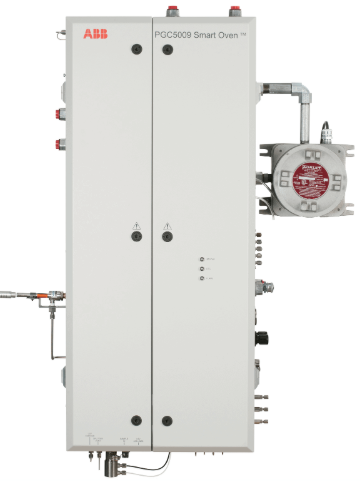
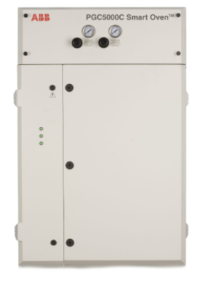
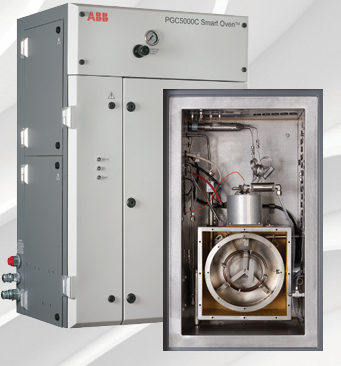
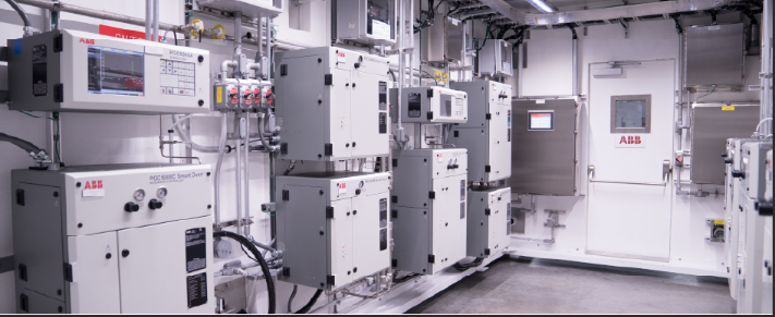
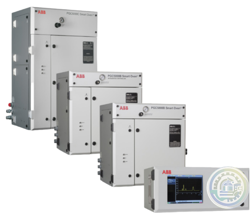
ABB PGC5000 Temperature programmed gas chromatograph Gas Control
-
ABB PGC5000 Temperature programmed gas chromatograph Safety area classification
-
ABB PGC5000 Temperature programmed gas chromatograph Introduction
-
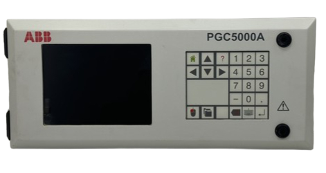
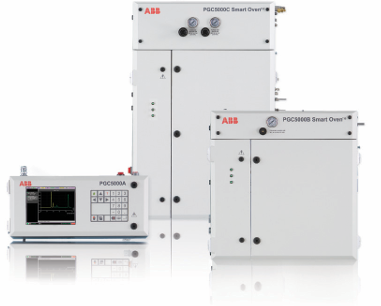
ABB PGC5000 Series gas chromatographs PGC5000A Generation 2 master controller Application flexibility
-
ABB PGC5000 Series gas chromatographs PGC5000A Generation 2 master controller Features
-
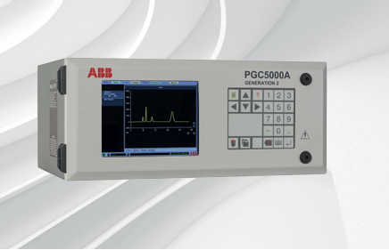
ABB PGC5000 Series gas chromatographs PGC5000A Generation 2 master controller
-
ABB Time Synchronization in PGC5000 Series Data System
-
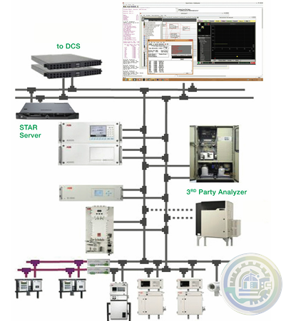
ABB VistaSTAR with PGC5000 Version 4 Data System Interface
- Bristol Babcock
- Rolls-Royce
- Aerotech
- APPLIED MATERIALS
- Basler
- SAACKE
- BENDER
- Kollmorgen
- MEGGITT
- METSO
- MITSUBISHI
- MTL
- HIMA
- Siemens
- BACHMANN
- AMAT
- DEIF
- DELTATAU
- EATON
- ELAU
- LAM
- SCHNEIDER
- Advantest
- ABB
- GE
- Emerson
- Motorola
- A-B
- KUKA
- Abaco
- HITACHI
- SST
- Vibro-Meter
- Rexroth
- Prosoft
- DFI
- Scanlab
- Reliance
- Parker
- Woodward
- MOOG
- NI
- FOXBORO
- Triconex
- Bently
- ALSTOM
- YOKOGAWA
- B&R
- UNIOP
- KONGSBERG
- Honeywell
- Omron
- CTI
- EPRO
- Tell:+86-18144100983
- email:kongjiangauto@163.com
- Application:wind/ petroleum/ chemical/ natural gas/ Marine/ mining/ aviation/ electronics/ steel/ nuclear power/ electric power/ coking/ air separation and so on
- Series:PLC/ DCS/ servo/ analog/ Ethernet/ digital/ redundant module/ tension system/ excitation/ generator management/ human-machine interface/ detection card/ sensor/ AC drive/ etc
Part Number IS200TPROH1C Manufacturer General Electric Country of Manufacture As Per GE Manufacturing Policy Series Mark VIe Function Module Availability In StockThe IS200TPROH1C is an Emergency Protection (TPRO) terminal board developed by GE. Three PPRO I/O packs are housed on the Emergency Protection (TPRO) terminal board. It has a pair of potential transformers (PTs) for bus and generator voltage input and conditions speed signal inputs for the PPROs. There are three DC-37 pin connectors on it, one on each side of the PPRO pack connectors. A cable leading to a Mark* VIe backup trip relay terminal board is accepted by each DC-37. TPROH1C has two pluggable blocks with 24 barrier terminals each. Do not inadvertently cross-connect the 240 V ac and dc voltages in 240 V ac applications. The peak voltage will be higher than the MOV rating, causing the MOV to fail. Most ac supplies have a grounded neutral, so if an unintended connection between the 125 V dc and the ac voltage is made, the sum of the ac peak voltage and the 125 V dc is applied to MOVs connected between dc and ground.

On the other hand, in 120 V ac applications, the MOV rating can endure the peak voltage without failing. IS200TPROH1C Compatibility TPROH1C is a simplex and TMR application that works with the PPRO I/O pack. TPROH#C links to three PPRO I/O packs in TMR systems. TPROH1CD and H12C both accept three PPROH1As for direct attachment and include DC-37 connections for three cables to the backup trip relay terminal boards. IS200TPROH1C Installation TPROH1C and a plastic insulator are mounted on a DIN-rail-mounted sheet metal carrier. The TPRO and insulator can also be mounted on a sheet metal assembly that bolts directly into a panel. Typical #18 AWG wires are used to connect speed signals and PT inputs to the terminal block.TEL:+8618144100983 The TPROH1C barrier terminal block can be removed to replace the board. The TPROH2C is a removable Euro-Block type terminal block that can be plugged in.
IS200TPROH1C Operation On terminals 31-48, nine-speed inputs are displayed. The consumer can get P24 output from Terminals 5, 9, and 11. The return path for the P24 output is Terminal 8 (MARET). ORing the 28 V power supply of I/O packs R, S, and T yield the P24 output. P24 V output can be accessed even if any of the I/O packs are turned off. Terminals 6, 10, and 12 are 4-20 mA inputs that are fanned to R, S, and T PPRO connections and are allocated for future control extensions. For the 4-20 mA input, Terminal 8 (MARET) serves as a return path. Diagnostics Electronic ID parts on the TPRO board and backup trip relay terminal board are scanned during power initiation. PPRO uses this data to verify that the hardware configuration is correct before initiating normal operations. Configuration When thermocouple inputs are used, all JPX, JPY, and JPZ jumpers should be in the (1, 4, 7, 10) position; when 4-20 mA inputs are used, all JPX, JPY, and JPZ jumpers should be in the (3, 6, 9, 12) position.
| User name | Member Level | Quantity | Specification | Purchase Date |
|---|


Please do not listen to the advice of non-professional engineers! Cause equipment damage!


wechat/whatsapp:
+86-181-4410-0983
Email: kongjiangauto@163.com
-
ABB NE810 3BSE080207R1 Network switch
-
ABB NE802 Network switch 3BSE080237R1
-
GE IS230TNRLH1B Relay Output DINrail Module
-
GE IS220PAICH1B Analog I/O Module
-
GE IS220PAICH1B Analog I/O Module
Copyright © 2009 - 2024 Cld , All Rights Reserved K-JIANG All rights reserved


