-
Alstom 029.232 446 Central Unit VME A32/D32 | COP 232.2
-
ABB REF610B11LCNP Feeder Protection and Control
-
A-B 1794-IN106 Input/Output Analog Modules
-
General Electric 029.381208 Converteam Controller Module
-
Eaton XIOC-BP-3 Moeller 3-Signal Module Backplane
-
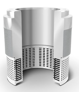
Emerson Fisher™ WhisperFlo™ Aerodynamic Noise Attenuation Trim
-
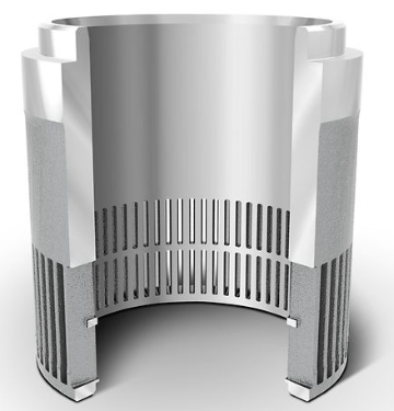
Emerson Fisher™ Whisper Trim™ I Cage
-
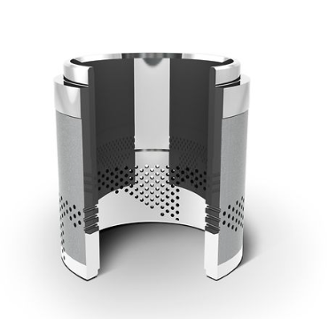
Emerson Fisher™ Whisper Trim™ III Cage
-
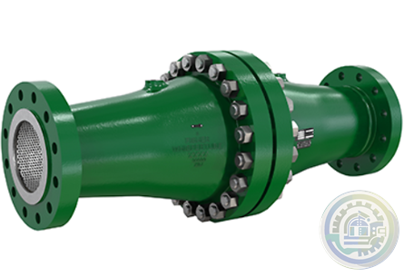
Emerson Fisher™ 6060 WhisperTube Modal Attenuator
-
Emerson Fisher™ easy-e™ EA SERIES Control Valve
-
Emerson Rosemount 8700 Series Magnetic Flowmeter Systems
-
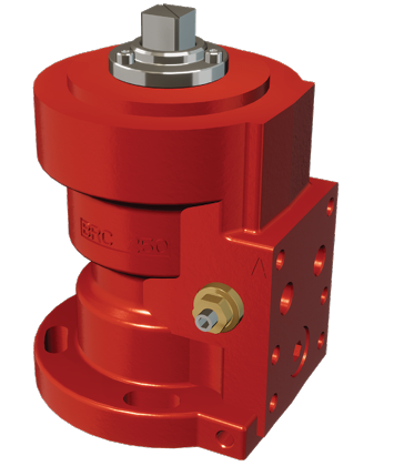
Emerson Damcos™ BRC 250 Hydraulic Double-acting Balanced Rotary Actuator 90° (Quarter-turn)
-
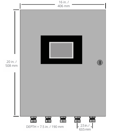
Emerson Model M250N Mounting of Rack Mount Enclosure
-
Emerson Model M250N Controlinc Network Controller System Configuration
-
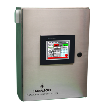
Emerson Controlinc Network Master Model M250 Version 5.2
-
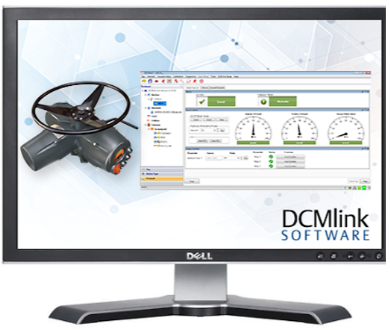
Emerson DCMlink Software
-
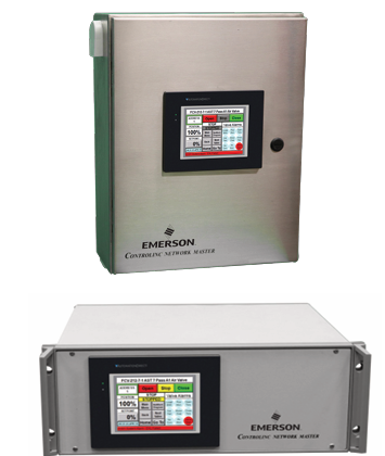
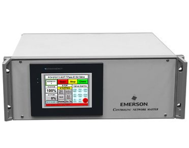
Emerson M250 Controlinc Network Master
-
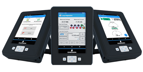
Emerson AMS Trex Device Communicator
-
Emerson AMS Trex™ Device Communicator with embedded Bluetooth® connectivity
-
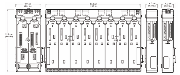
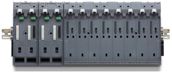
Emerson S-series Horizontal Carriers Product Description
-
Emerson S-series Horizontal Carriers Modular design allows flexible installation
-
Emerson S-series Horizontal Carriers
-
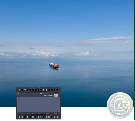
DEIF TAS-331DG AC transducer for active or reactive power
-
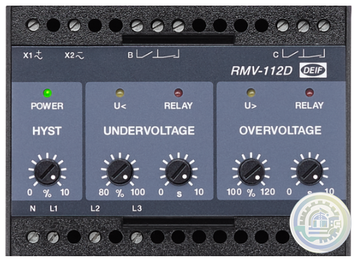
DEIF RMV-112D Undervoltage and overvoltage relay, U< and U>
-
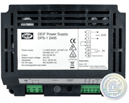
DEIF DPS-1 DC Power Supply
-
DEIF DM 400 hydro Integrated systems
-
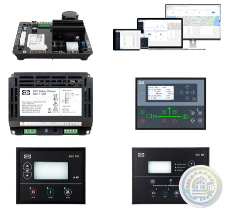
DEIF DBC-1 Battery charger
-
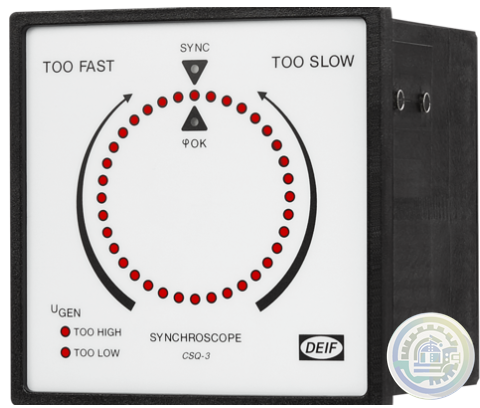
DEIF CSQ-3 Multi-function synchroscope
-
DEIF CODESYS Programming editor and debug
-
DEIF CODESYS Features Software - AWC 500 development package
-
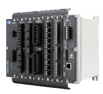
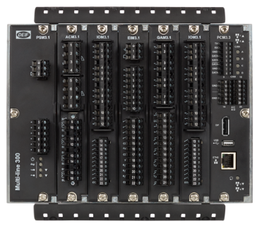
DEIF AMC 300 Features Advanced Programmable Controller
-
DEIF AMC 300 Performance and system design freedom
-
DEIF AMC 300 Flexible solution design options
-
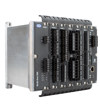
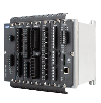
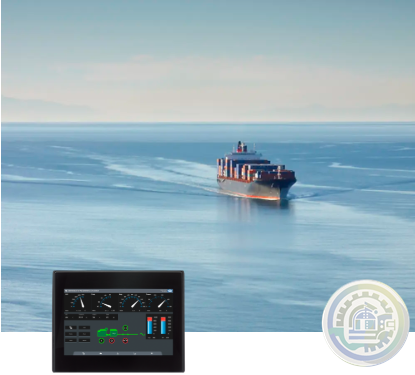
DEIF AMC 300 Advanced Programmable Controller
-
DEIF AGI 400 Features Advanced graphical interface
-
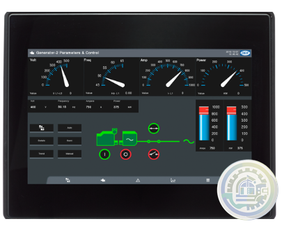
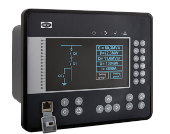
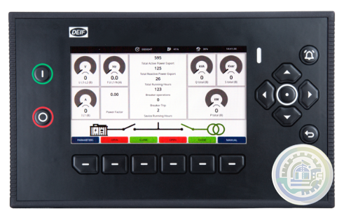
DEIF AGI 400 Advanced graphical interface
-
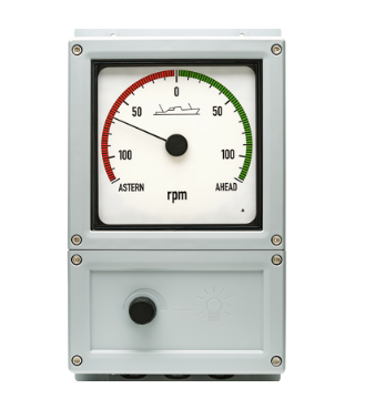
DEIF BRW-2 & BW Analogue illuminated bridge wing indicators
-
DEIF Basic control package for mobile generators
-
DEIF AWC 500 - G59/3 Integrated G59/3 protection turbine controller unit
-
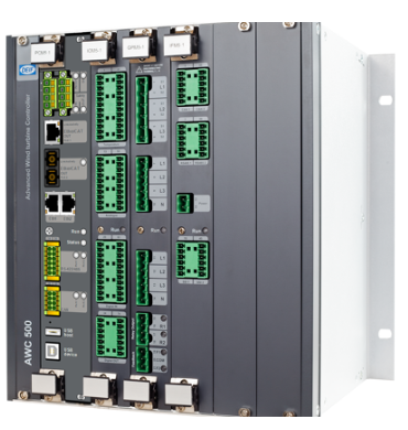
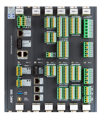
DEIF AWC 500 Advanced Controller
-
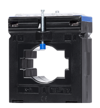
DEIF ASK & ASR Measuring transformer
-
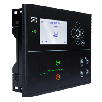
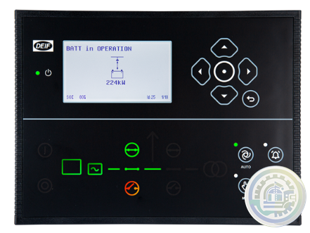
DEIF ASC-4 Battery Energy source, power source, or droop mode
-
DEIF ASC-4 Battery Automatic Sustainable Controller
-
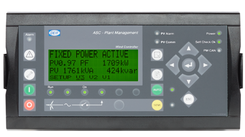
DEIF ASC plant management Ideal for self-consumption applications
-
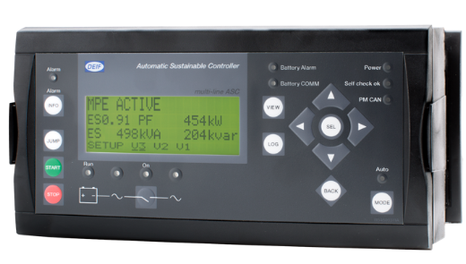
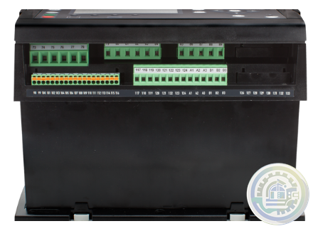
DEIF ASC plant management Automatic sustainable controller
-
DEIF AOP Additional operator panel
-
DEIF AMC 600 Fast, fail-safe, and secure system software
-
DEIF AMC 600 Wide range of protocols supported
-
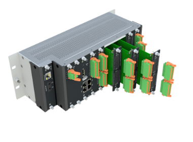
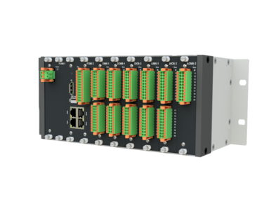
DEIF AMC 600 Programmable automation controller with EtherCAT based I/O
-
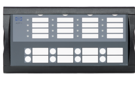
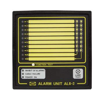
DEIF AL8-2 Alarm panel
-
DEIF AGC 150 Hybrid Advanced Genset Controller
-
DEIF AGC 150 PMS Lite Simple power management controller
-
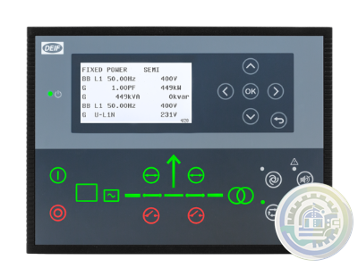
DEIF AGC 150 Generator Advanced Genset Controller
-
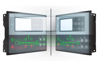
DEIF AGC 150 Remote Display Remote access and control unit
-
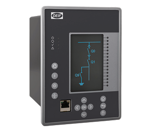
DEIF MVR-250 series Medium Voltage Relay
-
DEIF MVR-210 series Medium Voltage Relay
-
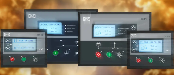
DEIF The SGC series
-
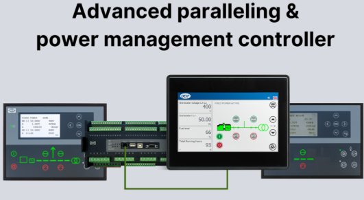
DEIF Advanced paralleling and power management controllers
-
DEIF Engine and single genset controllers
-
DEIF iE 350 Marine Highly flexible and cybersecure intelligent energy controller
-
DEIF iE 250 Marine Versatile and cybersecure intelligent energy controller for maritime applications
-
DEIF iE 150 Marine Simple and effective power management
-
DEIF iE 150 Marine Cost-effective and flexible controller for coastal, harbour, and inland vessels
-
DEIF iE 650 PLC Fast, fail-safe, and secure system software
-
DEIF iE 650 PLC Performance and flexibility with module concept
-
DEIF iE 650 PLC Extreme robust Programmable Automation controller with EtherCAT based I/O
-
DEIF iE 350 PLC Performance and system design freedom
-
DEIF iE 350 PLC Robust right out of the box
-
DEIF Advanced Features of the iE 350 PLC Controller
-
DEIF iE 250 PLC Versatile and modular intelligent energy PLC controller
-
DEIF XL / BW / BRW-2 Illuminated indicators
-
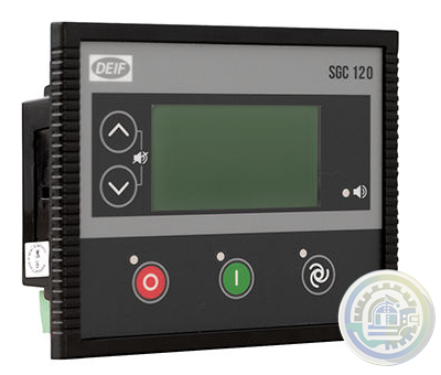
DEIF SGC 120/121 Single Genset Controllers
-
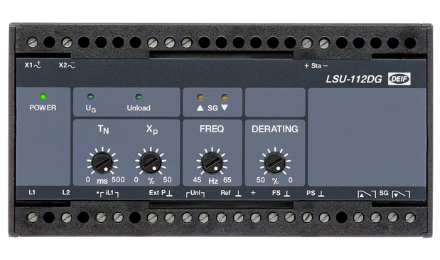
DEIF Load Sharing Unit LSU-112DG
-
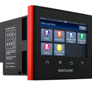
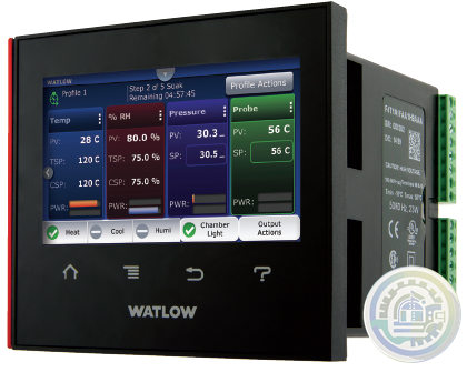
Watlow F4T Base Specifications
-
Watlow F4T Key Features and Options 1/4 DIN Process Controller
-
Watlow F4T 1/4 DIN Process Controller Features and Benefits
-
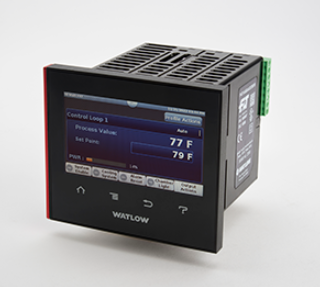
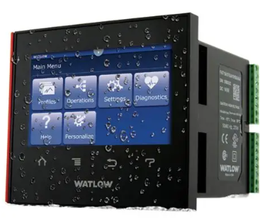
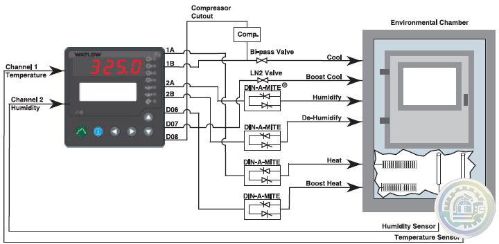
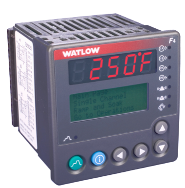
Watlow F4T 1/4 DIN Process Controller
-
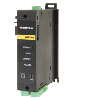
Watlow ASPYRE® AT Power Controllers Specifications
-
Watlow ASPYRE® AT Power Controllers
-
Watlow ASPYRE® DT Power Controllers Features and Benefits
-
Watlow ASPYRE® DT Power Controllers
-
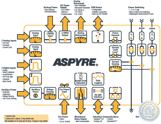
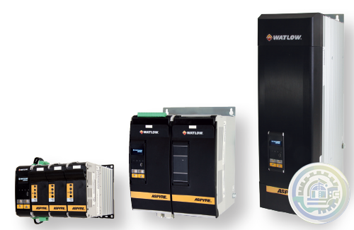
Watlow ASPYRE® Power Controllers Features and Benefits
-
Watlow ASPYRE® Power Controllers
-
Watlow SERIES F4 Specifications 1/4 DIN Ramping Controllers
-
Watlow SERIES F4 1/4 DIN Ramping Controllers Features and Benefits
-
Watlow SERIES F4 1/4 DIN Ramping Controllers
-
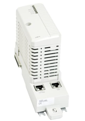
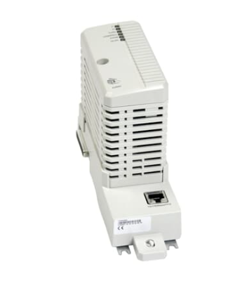
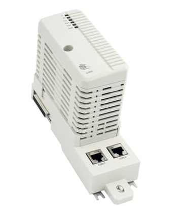
ABB CI869 Ability™ System 800xA® hardware selector
-
CI867A ABB Ability™ System 800xA® hardware selector
-
CI860 ABB Ability™ System 800xA® hardware selector
-
ABB CI855 Ability™ System 800xA® hardware selector
-
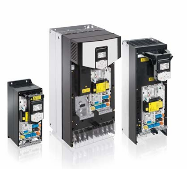
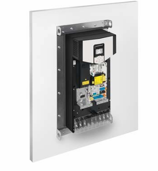
ABB Single drive modules ACS880-01, frame sizes R1, R8 and R5, IP20
-
ABB Single drive modules, ACS880-01 with option +P940
-
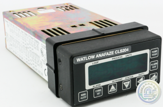
Watlow Anafaze CLS200 Controller 204-1200000
-
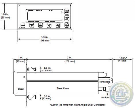
Watlow SERIES CLS200 Specifications
-
Watlow SERIES CLS200 DAC and SDAC Modules
-
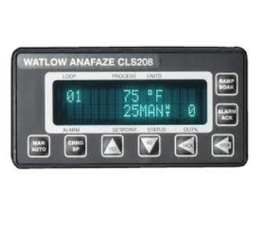
Watlow SERIES CLS200 Powerful line of controllers
-
ALSTOM ALSPA®MV500 Drive Dependable Drives – Reliable Support
-
ALSTOM ALSPA®MV500 Drive Small in Size – Big on Features
-
ALSTOM ALSPA®MV500 Drive Easy to use – Simple to install
-
ALSTOM Common Programming Tools for all Drives and Automation
-
ALSTOM Drives ALSPA DRIVE RANGE Drive solutions for all applications
-
ALSTOM Power Conversion ALSPA DRIVE RANGE Drive solutions for all applications
-
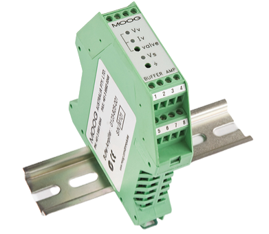
MOOG G123-825-001 Buffer Amplifier
-
Emerson AMS 3120 Bearing-Vibration Monitor
-
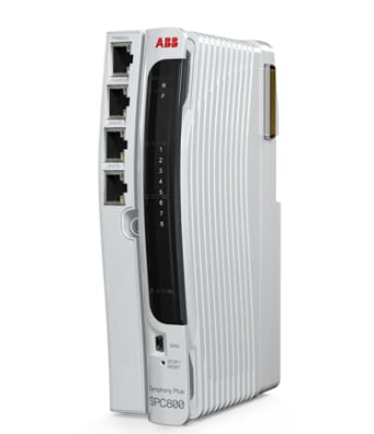
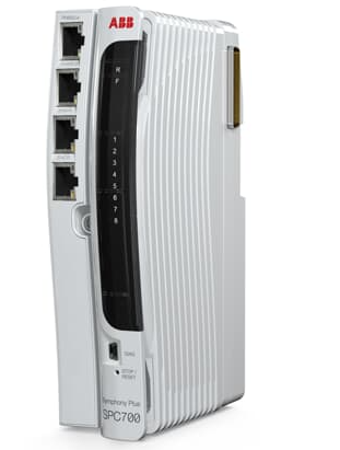
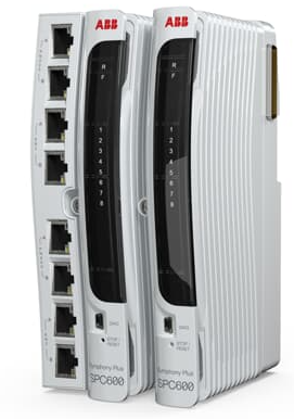
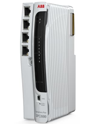
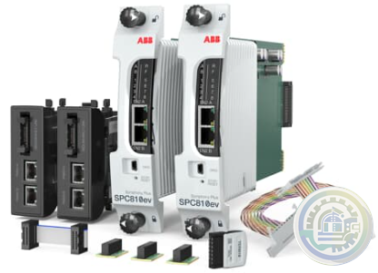
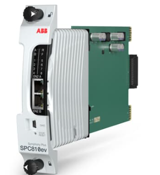
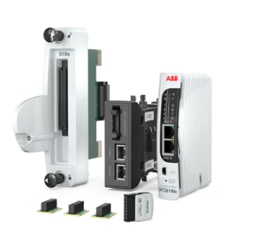
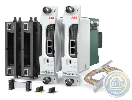
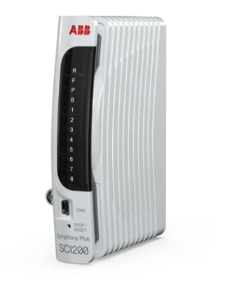
ABB SPC800VK01 Ability™ Symphony® Plus Hardware Selector
- Studer
- Watlow
- AEG
- ADVANCED
- KEBA
- Bristol Babcock
- Rolls-Royce
- Aerotech
- APPLIED MATERIALS
- Basler
- SAACKE
- BENDER
- Kollmorgen
- MEGGITT
- METSO
- MITSUBISHI
- MTL
- HIMA
- Siemens
- BACHMANN
- AMAT
- DEIF
- DELTATAU
- EATON
- ELAU
- LAM
- SCHNEIDER
- Advantest
- ABB
- GE
- Emerson
- Motorola
- A-B
- KUKA
- Abaco
- HITACHI
- SST
- Vibro-Meter
- Rexroth
- Prosoft
- DFI
- Scanlab
- Reliance
- Parker
- Woodward
- MOOG
- NI
- FOXBORO
- Triconex
- Bently
- ALSTOM
- YOKOGAWA
- B&R
- UNIOP
- KONGSBERG
- Honeywell
- Omron
- CTI
- EPRO
- Tell:+86-18144100983
- email:kongjiangauto@163.com
- Application:wind/ petroleum/ chemical/ natural gas/ Marine/ mining/ aviation/ electronics/ steel/ nuclear power/ electric power/ coking/ air separation and so on
- Series:PLC/ DCS/ servo/ analog/ Ethernet/ digital/ redundant module/ tension system/ excitation/ generator management/ human-machine interface/ detection card/ sensor/ AC drive/ etc
There are two models of RPS
Baseplates, which are identical except for the length of the adapter connection cable.
The IC693ACC340 has a 0.125-meter cable, and the IC693ACC341 has a 0.6-meter cable.
Redundant Power Supply Adapter The Redundant Power Supply Adapter plugs into a
standard IC693 PLC baseplate’s power supply slot.
It has a connector that mates to the RPS Baseplate’s adapter connection cable.
It also contains the backup battery and serial port connector for the PLC (backup battery and
serial port connector are not functional on the individual power supplies).

The IC693 Redundant Power Supply System consists of a Baseplate and an Adapter, described below.
Redundant Power Supply (RPS) Baseplate The Redundant Power Supply Baseplate
has slots for two standard IC693 power supplies, an attached adapter
connection cable that connects to the Power Supply
Adapter, status LED lights, a 24VDC user output, and status relay outputs.
Redundant Power Supply Baseplate Mounting Positions
The RPS Baseplate can mount in one of three basic positions on an enclosure panel:
· Above the IC693 PLC baseplate. Use the IC693ACC341 Redundant Baseplate model (with 0.6-meter cable).
· To the left of the IC693 PLC baseplate. Use the IC693ACC340 Redundant Baseplate model (with0.125-meter cable).
· Below the IC693 PLC baseplate. Use the IC693ACC341 Redundant Baseplate model (with 0.6-meter cable).
These three positions are illustrated below.

The RPS Baseplate should be grounded in the same manner as any IC693 PLC baseplate. Each ground
wire should consist of a size 12 AWG or larger wire with a ring terminal crimped to each end. One end
of each ground wire should be securely fastened to a conductive surface on the mounting panel (this often
requires removing the paint from the panel at the spot where the ground wire is fastened). If all ground
wires are connected to one point, ensure that the method (typically using a stud, nuts, and lock washers) is
approved by applicable electrical codes. The next figure shows an example ground connection for each
of the following components:

· RPS Baseplate and PLC Baseplate. One end of the ground wire should be mounted under the
head of the mounting bolt (with star lock washer and flat washer) in one of the baseplate’s
slotted mounting holes; the other end should connect to the grounding point on the panel.
· RPS Adapter Module. The RPS Adapter’s ground wire is supplied as part of the RPS cable.
See the section “IC693ACC350 Redundant Power Supply Adapter” for details and a picture of
this wire. Connect it to the grounding point on the panel.
We have the same series of models in stock.
If you don't find the model you need, please contact us and we will provide you with an official quotation!
GE IC690PRA001 wall mounting bracket |
GE IC690PRA002 40 amp PS wall mounting bracket |
GE IC690PRM005 FIELD POWER SUPPLY 24VDC 5A |
GE IC690PRM010 FIELD POWER SUPPLY 24VDC 10A |
GE IC690PRM120 FIELD POWER SUPPLY 24VDC 20A |
GE IC690PRM210 100-240AC or 100-300DC SUPPLY 24VDC 10A |
GE IC690PRM240 FIELD POWER SUPPLY 24VDC 40A |
GE IC690PRS010 dual-input, diode Redundancy module |
GE IC690PRS020 mofset redundancy module |
GE IC690PRS040 2x40 mofset redundancy module |
GE IC690PWR024 Field Power Supply 24 VDC 5 Amps |
GE IC690PWR124 Field Power Supply 24 VDC 10 Amps |
GE IC690RBK001 Rechargable battery kit |
GE IC690RBT001 Rechargable battery kit |
GE IC690USB128 128Meg USB memory stick |
GE IC692CPU211RR Series 90-20 CPU |
GE IC692MAA541RR 16 AC input/ 12 Triac Output 120 Vac PS |
GE IC692MDR541RR 16 AC input/ 12 Relay Output 120 Vac PS |
GE IC692MDR741RR 16 DC input/ 12 Relay Output 120 Vac PS |
GE IC693ACC300 Input Simulator Module |
GE IC693ACC300LT Input Simulator Module (LT) |
GE IC693ACC300RR Input Simulator Module |
GE IC693ACC301 Replacement Battery, CPU & PCM |
| User name | Member Level | Quantity | Specification | Purchase Date |
|---|


Please do not listen to the advice of non-professional engineers! Cause equipment damage!


wechat/whatsapp:
+86-181-4410-0983
Email: kongjiangauto@163.com
-
Alstom 029.232 446 Central Unit VME A32/D32 | COP 232.2
-
ABB REF610B11LCNP Feeder Protection and Control
-
General Electric 029.381208 Converteam Controller Module
-
Vibro-meter VM600-ABE042 204-042-100-011 Precision Control Module
-
Vibro-meter vmf-MPC4 200-510-111-034 200-510-070-113 Module
Copyright © 2009 - 2024 Cld , All Rights Reserved K-JIANG All rights reserved


