-
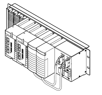
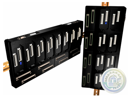
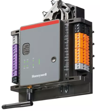
Kollmorgen AKT2G-AC-FAN-001 fan cartridge
-
Kollmorgen AKT-AN-820-000 8-Channel Analog Input Terminal
-
Kollmorgen 4-Channel Analog Input Terminal (AKT-AN-420-000)
-
METSO D201379 PC Board PLC & ADD-ON Board
-
Metso PDP403 Distributed Processing Unit
-
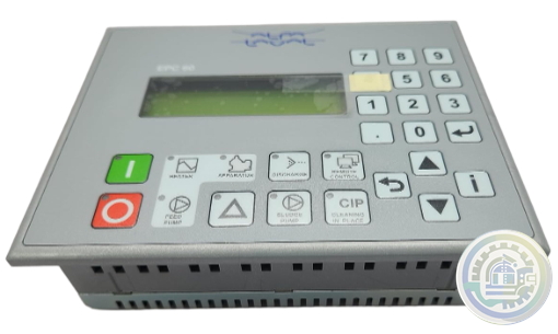
Alfa Laval EPC 60 Retrofit kit
-
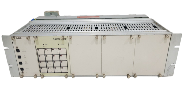
ABB Digital annunciator unit SACO 64D4
-
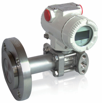
ABB Model 264DD Differential/Gauge
-
ABB Alarm annunciators
-
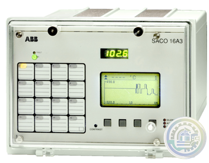
ABB SACO 16 A3 Analog Annunciator Unit
-
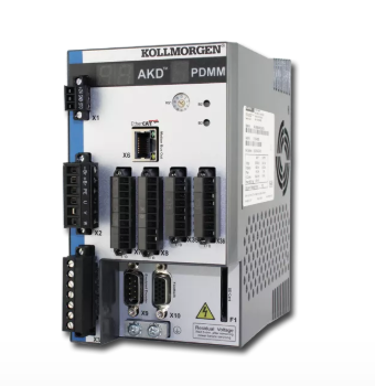
Kollmorgen AKD PDMM® Programmable Drive, Multi-Axis Master
-
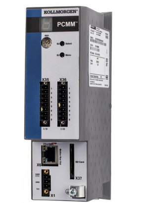
Kollmorgen PCMM: Programmable Controller, Multi-Axis Master
-
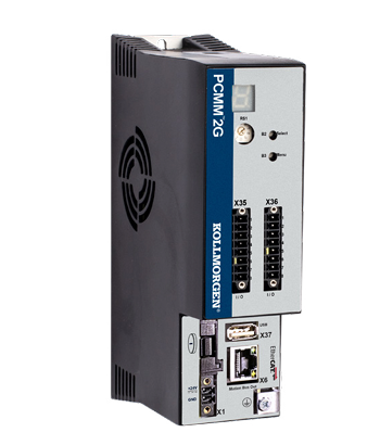
Kollmorgen PCMM2G: Next-Generation Performance in a Powerful, Compact Controller
-
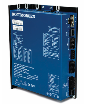
Kollmorgen P80630 Stepper Drive
-
Kongsberg Maritime System and vessel conversions
-
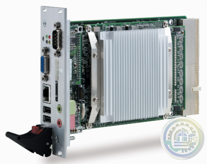
ADLINK CPCI-3840 3U CompactPCI Intel® Pentium® M Processor Module
-
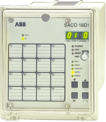
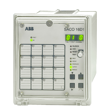
ABB Digital Annunciator Unit SACO 16D1
-
ABB SACO16D1-AA Digital Annunciator Unit
-
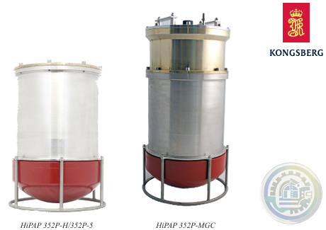
Kongsberg HIPAP® 352P PORTABLE HIGH PRESICION ACOUSTIC POSITIONING
-
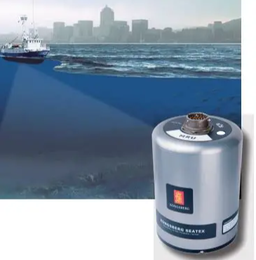
Kongsberg MRU 5 Motion Reference Unit
-
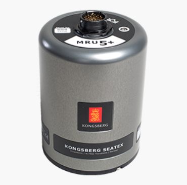
Kongsberg MRU 5+ Motion Reference Unit
-
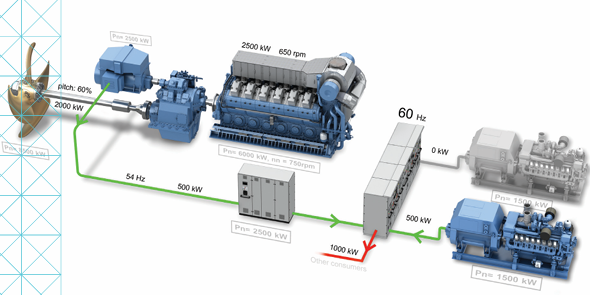
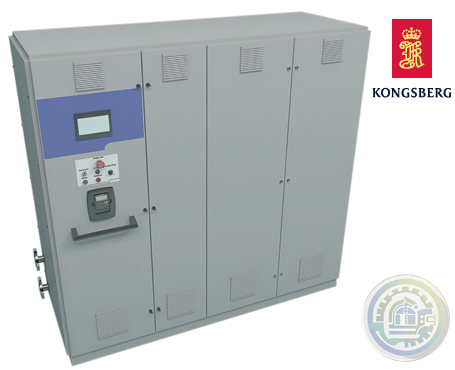
Kongsberg KONGSBERG MARITIME PROPULSION SYSTEMS Active Front End (AFE)
-
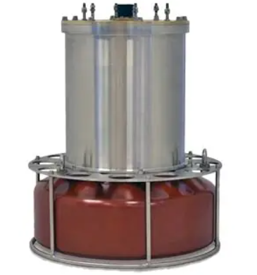
Kongsberg HiPAP 352P Portable acoustic positioning system
-
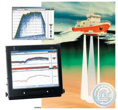
Kongsberg EA600 New generation precision hydrographic echo sounder
-
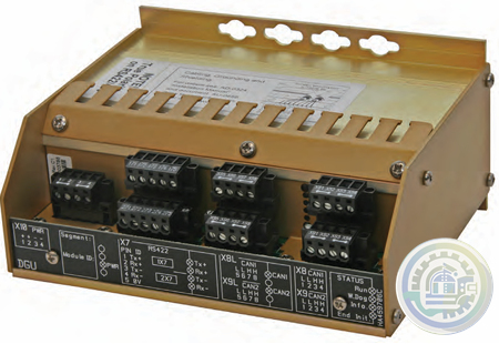
Kongsberg Digital Governor Unit (DGU) AutoChief® 600
-
Kongsberg AutoChief® 600 Propulsion Control System
-
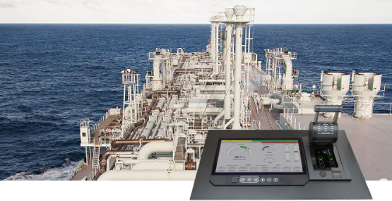
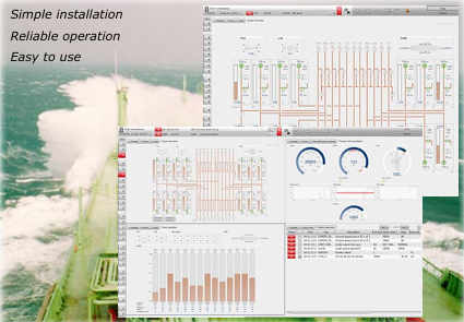
Kongsberg K-Chief Vessel Automation System
-
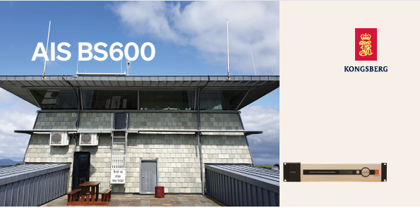
Kongsberg AIS BS600 Automatic Identification System - Base Station
-
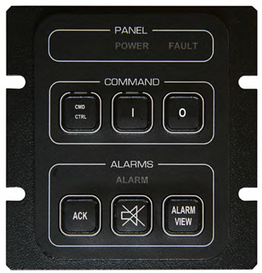
Kongsberg K-Chief 600 Alarm and Command Panel
-
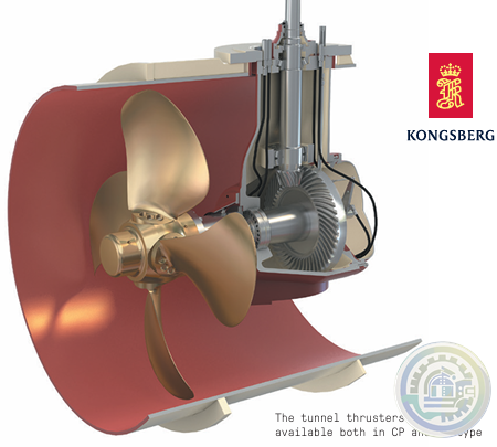
Kongsberg Tunnel Thrusters Type TT FP
-
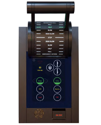
Kongsberg AutoChief®600 Lever Telegraph Unit (LTU11)
-
YOKOGAWA Model AW810D Wide Area Communication Router
-
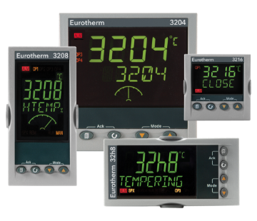
Watlow Eurotherm® 3200 Temperature/Process Controller
-
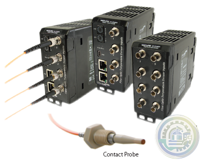
Watlow EtherCAT®, Fiber Optic Temperature Measurement and Control System
-
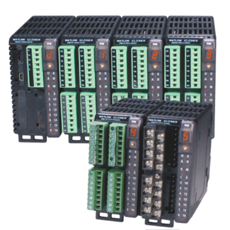
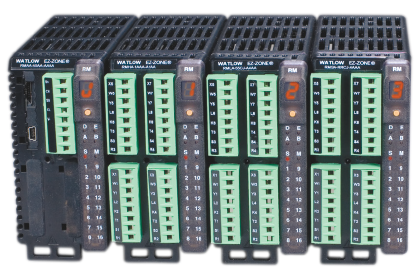
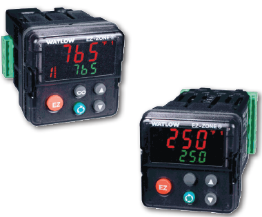
Watlow EZ-ZONE® RM Modular Controller Family
-
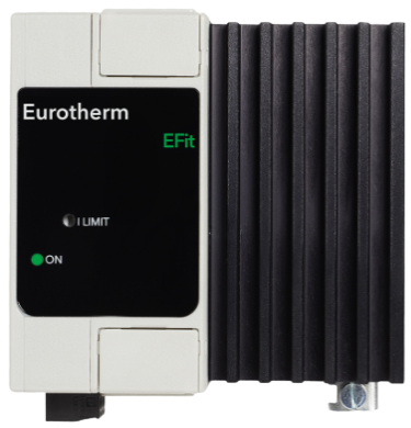
Watlow EFit SCR Power Controller
-
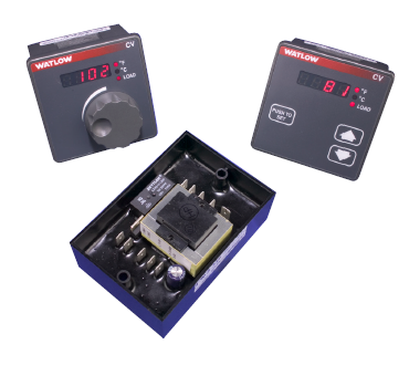
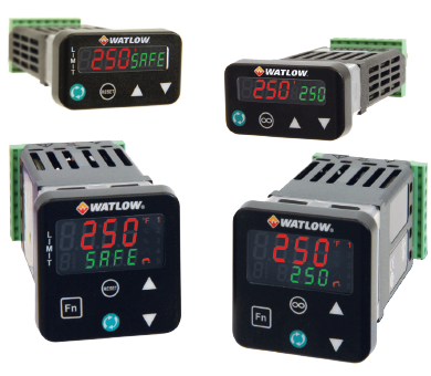
Watlow Basic Temperature and Limit Controllers
-
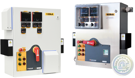
Watlow’s New WATCONNECT® Control Panels
-
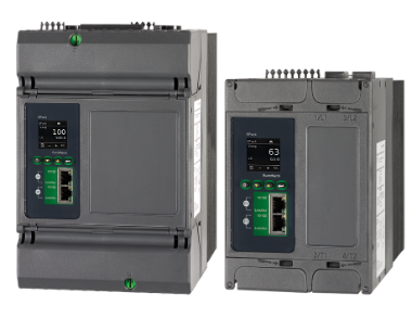
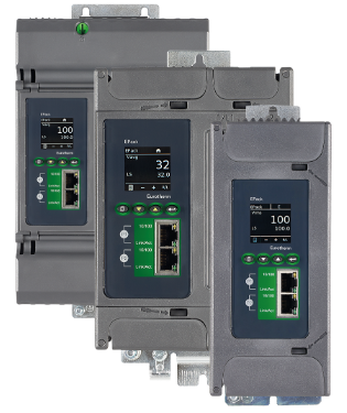
Watlow EPack-2PH Compact SCR Power Controllers
-
Watlow Large and Extra-Large WATCONNECT® Panels
-
Watlow Eurotherm® EPack™ compact SCR power controllers-1PH -2PH -3PH
-
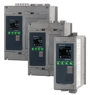
Watlow Eurotherm® EPack™ Lite Compact SCR Power Controllers
-
Watlow EPack™ Lite-1PH Compact SCR Power Controllers
-
Watlow’s new SERIES LS offers fixed limit set point temperature values
-
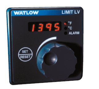
Watlow The SERIES LV limit family
-
Watlow’s family of microprocessor- based limit controllers SERIES LF
-
Watlow The EZ-ZONE RM controller simplifies thermal system management
-
Watlow The PM LEGACY™ series panel mount controller
-
Watlow EZ-ZONE® Remote User Interface (RUI)
-
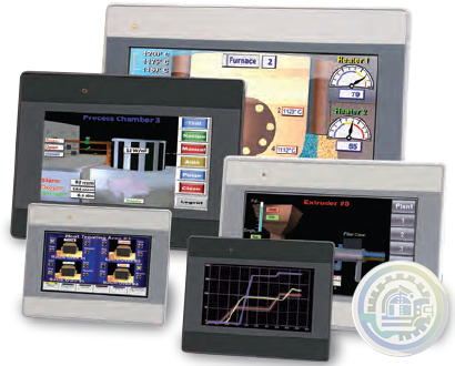
Watlow Silver Series EM Operator Interface Terminal
-
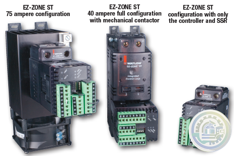
The EZ-ZONE® ST integrated solid state controller from Watlow®
-
YOKOGAWA Cooling Water Pump Failure Prediction Monitoring
-
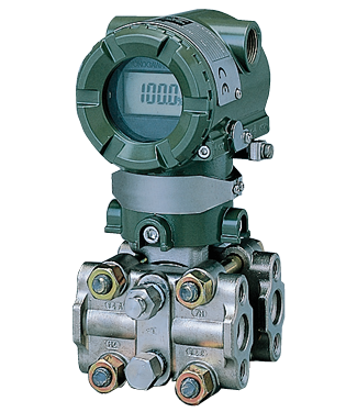
YOKOGAWA EJA Series Differential Pressure and Pressure Transmitters
-
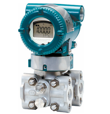
YOKOGAWA EJA110E Diff erential Pressure Transmitter
-
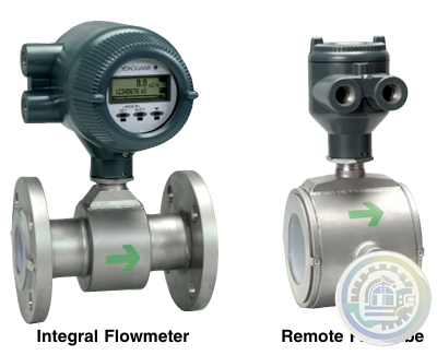
YOKOGAWA AXF Magnetic Flowmeter Series
-
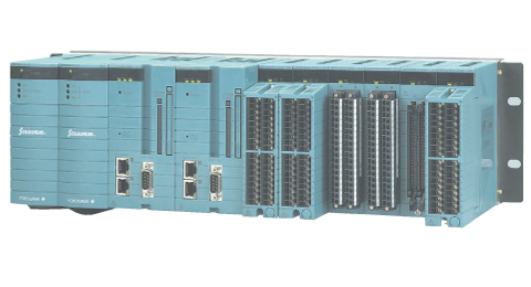
YOKOGAWA Turbomachinery Controller Overview (FCN-500/FCN-RTU)
-
YOKOGAWA STARDOM FCN-RTU Autonomous Controller
-
YOKOGAWA FCN Autonomous Controller Hardware (FCN-100)
-
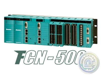
YOKOGAWA STARDOM FCN-500 Autonomous Controller
-
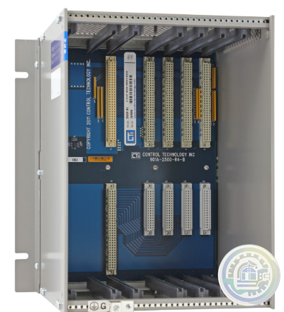
CTI 2500-R4 Four-Slot Base with High-Speed Channel
-
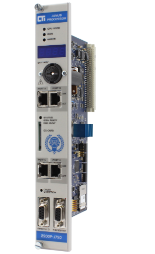
CTI 2500P-J750 Janus PAC with 3MB Project Memory
-
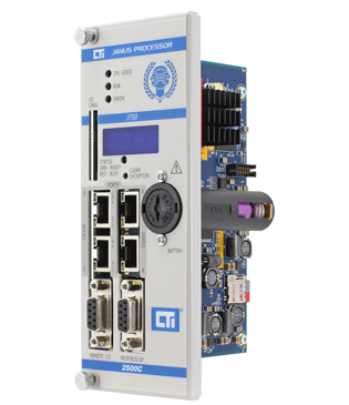
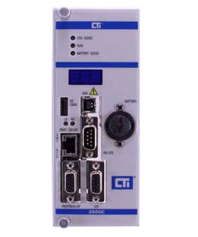
CTI 2500C-J750“Janus”Compact Programmable Automation Controller
-
CTI 2500 Series® Compact Programmable Controllers
-
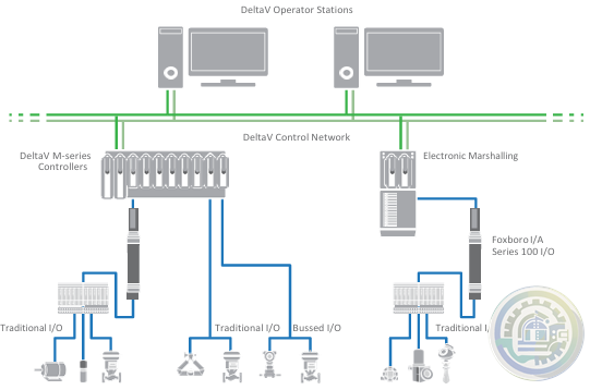
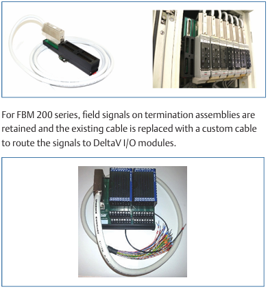
Emerson DeltaV™ Flex.Connect Solutions for Foxboro™ I/A Series 100 I/O
-
Emerson Modernization of Foxboro I/A Series® Systems to the DeltaV™ System
-
Foxboro DCS Fieldbus Modules for APACS+™ Automation Systems
-
Foxboro Evo™ Process Automation System
-
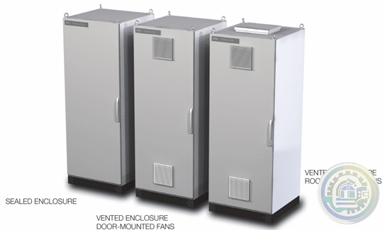
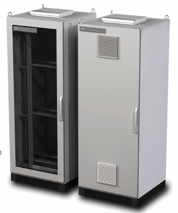
Foxboro™ DCS G61 Tricon Termination Enclosure
-
Foxboro G60 Tricon System Enclosure I/A Series® HARDWARE
-
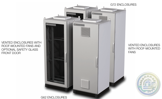
Foxboro G62 and G72 Tricon System and Termination Enclosures
-
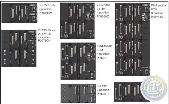
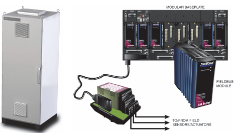
Foxboro I/A Series® Hardware DIN Rail Mounted Fieldbus Module Baseplate
-
Kongsberg K-Chief 600 Marine automation system
-
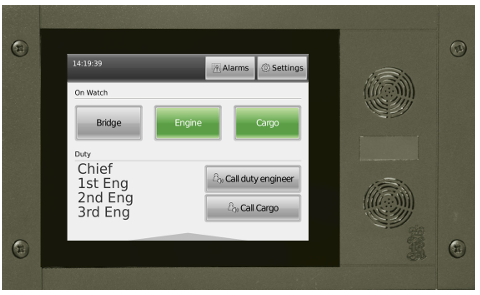
Kongsberg WCC 600 Watch Call Panels
-
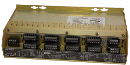
Kongsberg Distributed Processing Units Remote Digital Output (RDo-16xe)
-
Woodward EM‐80 and EM‐300 Actuators All‐Electric Actuator System
-
Foxboro DCS FBM for Migration of Bailey® Systems
-
Foxboro Migration with FCP280 and DCS FBMs
-
Foxboro DCS Fieldbus Modules for Siemens APACS+™ Automation Systems
-
Foxboro 200 Series Baseplate Module Mounting
-
Foxboro Standard 200 Series Subsystem Overview
-
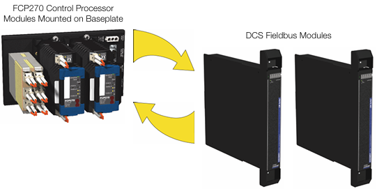
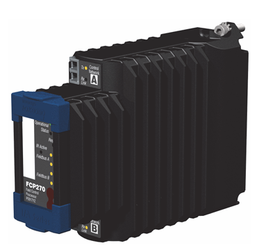
Foxboro Field Control Processor 270 (FCP270)
-
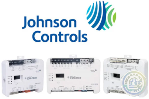
Johnson Controls DIS1710 Local Controller Display Installation Instructions
-
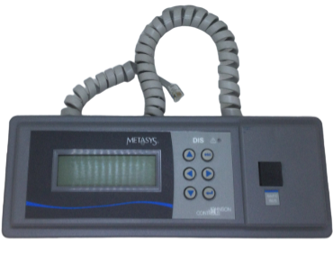
Johnson Controls FX-DIS Local Controller Display
-
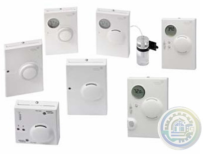
Johnson Controls WRZ Series Wireless Room Sensors
-
Woodward EM-80/EM-300 Actuator System
-
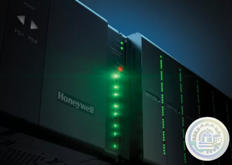
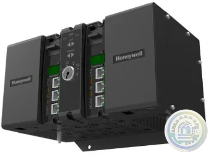
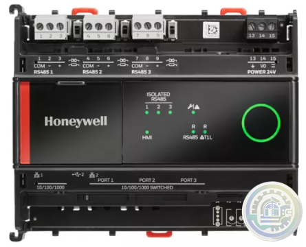
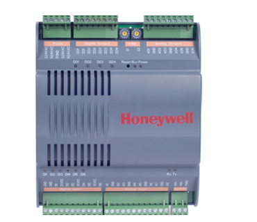
Honeywell ControlEdge™ PLC Modular Controllers
-
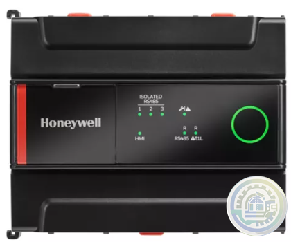
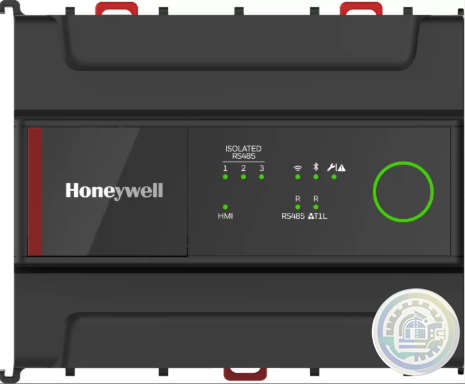
Honeywell CONTROLEDGE PCD Compact, Cyber Secure Control System
-
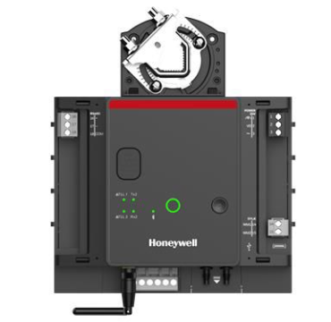
Honeywell M6410A, M7410F Non-Spring Return Cartridge Globe Valve Actuator
-
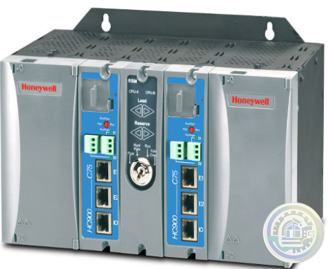
Honeywell ControlEdge™ HC900 How Does It Work?
-
Honeywell ControlEdge HC900 controller
-
Honeywell HC900 Functional Overview
-
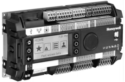
Honeywell Optimizer Advanced Controllers are a family of next generation integration & plant controllers
-
Honeywell Optimizer Advanced Controller
-
Honeywell Excel Web II Control System
-
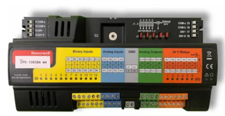
Honeywell CPO-PLANT Controller area of the site
-
Honeywell ComfortPoint Niagara T1L VAV Controller
-
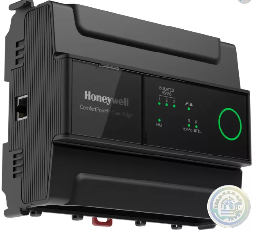
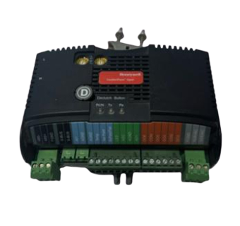
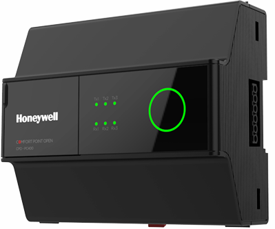
Honeywell ComfortPoint™ Open Plant Controller
-
Honeywell ComfortPoint Open CP-EXPIO (EXPANSION IO BOARD)
-
Honeywell ComfortPoint Open CPO-VAV2A-US (UNITARY CONTROLLER)
-
Honeywell ComfortPoint™ Open CPO-PC400 Plant Controller
-
Honeywell I/O MODULES EXPANSION MODULES & WIRING ADAPTER
-
Honeywell CPO-DIO ComfortPoint Open (DIGITAL I/O CONTROLLER)
-
Honeywell CP-Core ComfortPoint Open
-
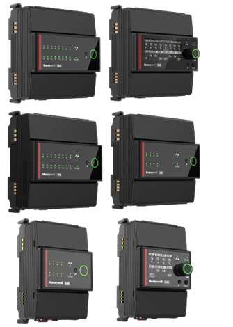
Honeywell CPO-IO830A ComfortPoint Open MIXED I/O MODULE
-
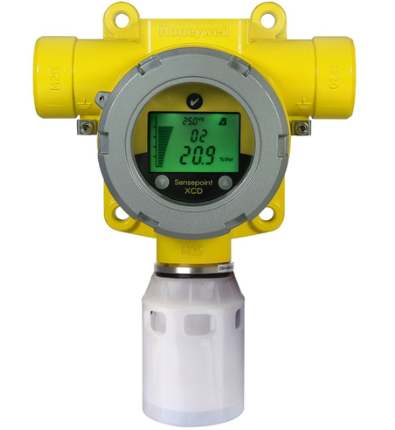
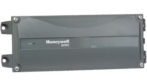
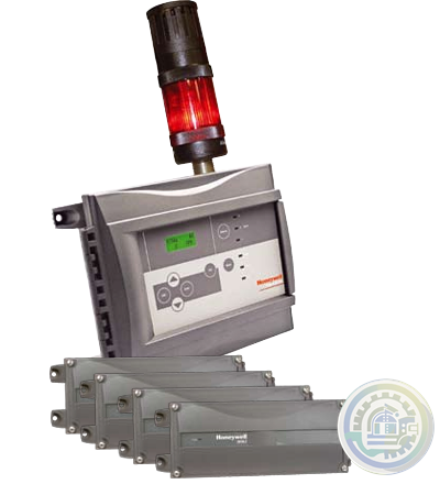
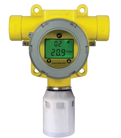
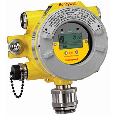
Honeywell Sensepoint XCD
- Baldor
- Glassman
- Johnson Controls
- Studer
- Watlow
- AEG
- ADVANCED
- KEBA
- Bristol Babcock
- Rolls-Royce
- Aerotech
- APPLIED MATERIALS
- Basler
- SAACKE
- BENDER
- Kollmorgen
- MEGGITT
- METSO
- MITSUBISHI
- MTL
- HIMA
- Siemens
- BACHMANN
- AMAT
- DEIF
- DELTATAU
- EATON
- ELAU
- LAM
- SCHNEIDER
- Advantest
- ABB
- GE
- Emerson
- Motorola
- A-B
- KUKA
- Abaco
- HITACHI
- SST
- Vibro-Meter
- Rexroth
- Prosoft
- DFI
- Scanlab
- Reliance
- Parker
- Woodward
- MOOG
- NI
- FOXBORO
- Triconex
- Bently
- ALSTOM
- YOKOGAWA
- B&R
- UNIOP
- KONGSBERG
- Honeywell
- Omron
- CTI
- EPRO
- Tell:+86-18144100983
- email:kongjiangauto@163.com
- Application:wind/ petroleum/ chemical/ natural gas/ Marine/ mining/ aviation/ electronics/ steel/ nuclear power/ electric power/ coking/ air separation and so on
- Series:PLC/ DCS/ servo/ analog/ Ethernet/ digital/ redundant module/ tension system/ excitation/ generator management/ human-machine interface/ detection card/ sensor/ AC drive/ etc
Power Supply Module Manufacturers ABB, Bailey Model(s)
ABB Bailey Infi 90, ABB Bailey Infi 90 and Net 90
Additional Information Modular Power System III (MPS III) 24V @ 17A, 48V @ 8.5A
Estimated Shipping Size Dimensions: 0.0" x 0.0" x 0.0" (0.0 cm x 0.0 cm x 0.0 cm)
Weight: 0 lbs 0.0 oz (0.0kg ) Power Supply Module

FEATURE
• Low-impedance busbar protection
• Stub and T-zone protection
• High functional reliability due to two independent measurement criteria:
- stabilized differential current algorithm
- directional current comparison algorithm
• Phase-by-phase measurement
• Reduced CT performance requirements
• High through-fault stability even in case of CT saturation
• Full solid-state busbar replica
• No switching of CT circuits
• Only one hardware version for
- 1 and 5 A rated currents
- all auxiliary supply voltages between 48 V DC and 250 V DC
- nominal frequencies of 50, 60 and 16.7 Hz
• Short tripping times independent of the plant’s size or configuration
• Centralized layout: Installation of hardware in one or several cubicles
• Distributed layout: Bay units distributed and, in the case of location close to the feeders, with short connections to CTs, isolators, circuit breakers, etc.
• Connections between bay units and central unit by fiber-optic cables
- maximum permissible length 1200 m
- for distributed and centralized layout
• fiber-optic connections mean interference proof data transfer even close to HV power cables
• Replacement of existing busbar protection schemes can be accomplished without restrictions (centralized layout) in the case of
substation extensions e.g. by a mixture of centralized and distributed layout
• Easily extensible

Below is a side internal view of the EL mechanism and the associated anti-pumping component.
When the opening pushbutton or coils are activated the opening shaft lever pushes down on point C of the anti-pump device.
This causes the device to side down slot D in direction of arrow B.
Then the trigger portion A moves out from between the closing push-button and the closing shaft lever.
So if the closing button or signal is held active and the opening button or signal is then activated.
The trigger A will pull out from between closing shaft lever and the closing push button.
Once the open signal is released the trigger A will come to rest under the closing push-button and will
not return between the closing shaft lever and closing push-button until the button or closing command is released.
The closing push button is operated by the closing coil (MC) directly by the shaft closing device.
This allows the anti-pumping device to prohibit closing by manual or electrical means.
| User name | Member Level | Quantity | Specification | Purchase Date |
|---|


Please do not listen to the advice of non-professional engineers! Cause equipment damage!


wechat/whatsapp:
Email: kongjiangauto@163.com
-
Vibro-meter vmf-RLC16-V111 200-570-101-015 200-570-000-111 Relay Card
-
Vibro-meter vmf-IOC4T 200560-101-017 200-560-000-111 I/O module
-
vmf cpum vmf-cmc16 200-530-111-013 200-530-100-014 Vibro-meter Monitoring system Modulee
-
Vibro-meter 200-595-045-114 | CPUM | Vibration Processor Module
-
Vibro-meter SIM-275A 200-582-500-013 state-of-the-art protection and monitoring module
Copyright © 2009 - 2024 Cld , All Rights Reserved K-JIANG All rights reserved


