
-
TMEIC KPAD-3122A A3XAP02 LCD Display With Key Pad
-
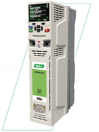
Nidec Drives S100-02463 General Purpose Micro AC Drive
-
Nidec Drives S100-02463 General Purpose Micro AC Drive
-
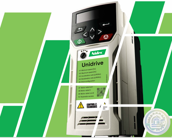
Nidec Drives S100-01D13 General Purpose Micro AC Drive
-
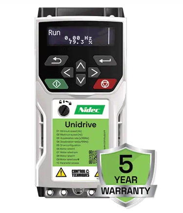
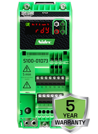
Nidec Drives S100-01D73 General Purpose Micro AC Drive
-
TMEIC High-voltage motors 21-L series
-
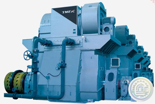
TMEIC MV Motor & Drive Solutions for Power Generation
-
TMEIC AC Motors Rolling Mills
-
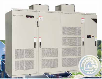
TMEIC TMdrive®-70 Medium Voltage 3-Level IEGT System Drive
-
TMEIC TMdrive®-70e2 Medium Voltage 3-Level IEGT System Drive
-
TMEIC TMdrive-MVe2 Reactive Power Control
-
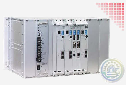
TMEIC Unified Controller nv Series
-
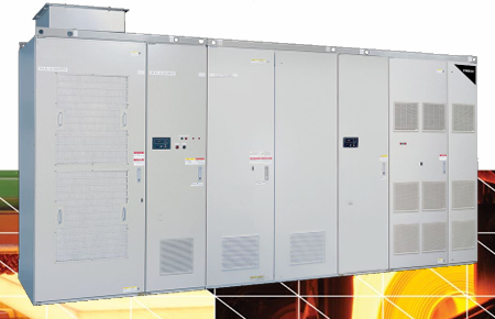
TMEIC TMdrive®-30 Medium Voltage 3-Level IGBT System Drive
-
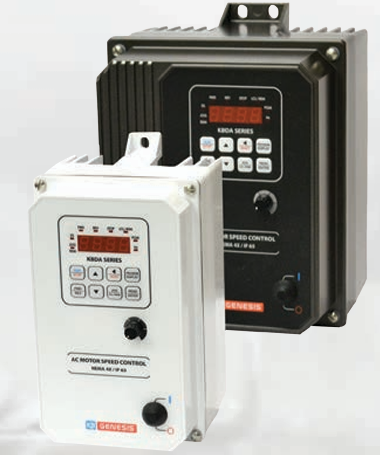
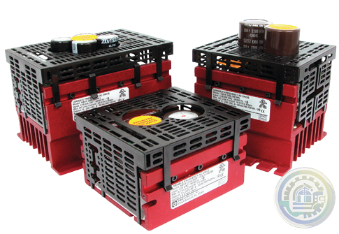
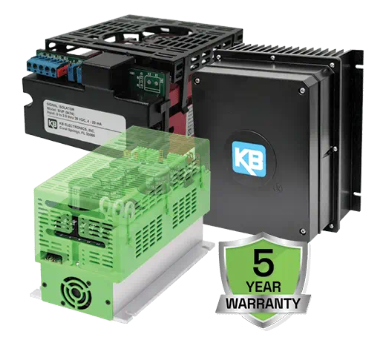
Nidec KBDA Digital AC Drive with CSP™*
-
Nidec KBMA Hybrid Drive™ A Digital AC Drive with Analog Interface
-
KBWA Hybrid Drive A Digital AC Drive with Analog Interface
-
KBVF Hybrid Drive™ A Digital AC Drive with Analog Interface
-
Nidec KBVF Micro AC drive
-
Nidec Unidrive M608 Industrial general-purpose drive
-
Nidec Unidrive M400 General Purpose AC Drives Series
-
Nidec Unidrive HS30 General Purpose AC Drives
-
Nidec NE200 & NE300 High Performance Vector Control Drives
-
Nidec Commander C Drive
-
Nidec Drives Commander S
-
Nidec Drives HVAC Drive H300 Efficiency and reliability in HVAC Specialist Drive
-
ABB RTU560 product line Reliable solutions for transmission and sub-transmission
-
Metso From Ore to Metals: Metso Outotec Offers Complete Solution to Recover Precious & Base Metals from Cengiz Mazidagi
-
Metso Life Cycle Services for mining
-
Metso Automation and Analyzer Services Courier® Legacy Upgrade
-
ABB PC D235 A – AC 800PEC CIO-FU Combined Input Output Data Sheet
-
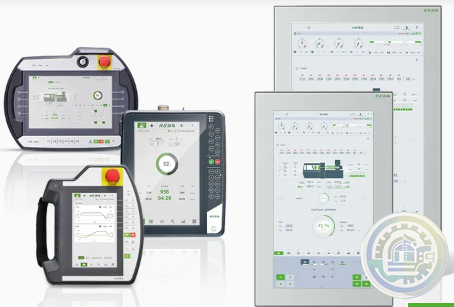
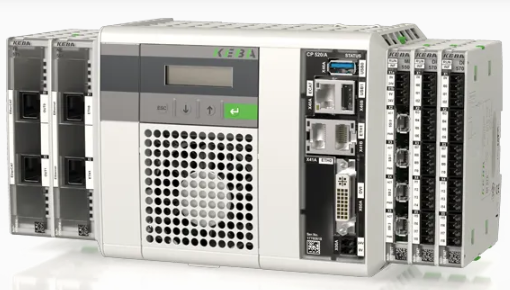
KEBA KeTop AP 524 The stationary, real-time-enabled multitouch panel
-
KEBA KePlast i8000 Premium class system for high-end machines
-
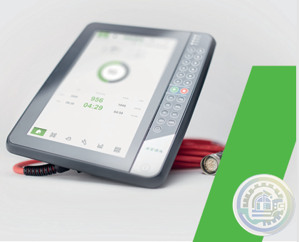
KEBA KeTop T135 Eco The mobile 7" web visualization in the ECO version
-
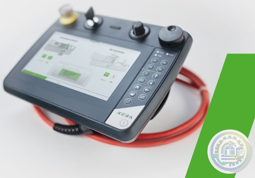
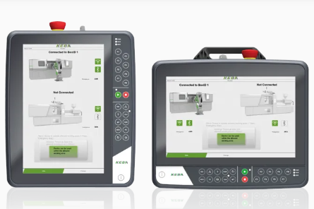
KEBA KeTop T135 The mobile 7" web visualization for all controls
-
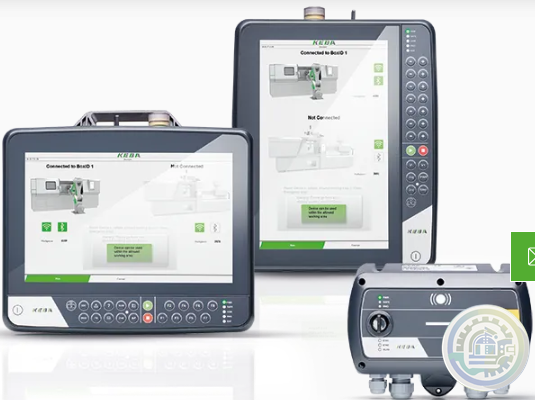
KEBA KeTop T150/T155 Safe Wireless
-
KEBA KeTop T200 The cost-effective replacement for stationary panels
-
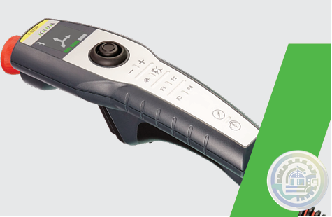
KEBA KeTop T150 / T155 Handheld terminal
-
KEBA KeTop T15x Mobile handheld terminal
-
ABB Stressometer® Systems Digital Transmission Unit PFSA107
-
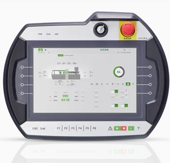
KEBA KeTop T70 Effective mobile operation, brilliant visualization
-
KEBA KeTop T10 directMove Operate robots easily and quickly with intuitive gestures
-
KEBA KeWheel The adaptive Rotary-Push Button
-
KEBA HMI - Human Machine Interface
-
KEBA Module AE 550 Artificial intelligence extension
-
KEBA Magnetic bearing drive system LeviTurb
-
GE AquaTrans™ AT868 Transmetteur de débit liquide à ultrasons Panametrics
-
Beckhoff EKM1101 | EtherCAT Coupler with ID switch and diagnostics
-
Beckhoff EK1101-0080 | EtherCAT Coupler with ID switch, Fast Hot Connect
-
Beckhoff EK1101-0010 | EtherCAT Coupler with ID switch, Extended Distance
-
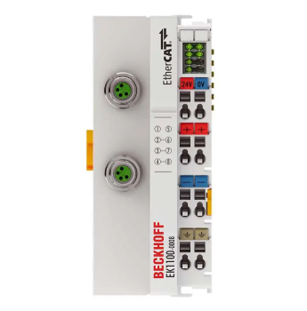
Beckhoff EK1101-0008 | EtherCAT Coupler with ID switch and M8 connection
-
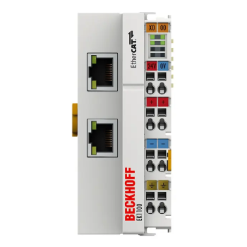
Beckhoff EK1101 | EtherCAT Coupler with ID switch
-
Beckhoff EK1000 | EtherCAT TSN Coupler
-
Beckhoff EK1100-0008 | EtherCAT Coupler with M8 connection
-
Beckhoff EC1100 | EtherCAT Coupler, RJ45, angled, push-in
-
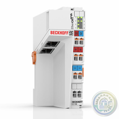
Beckhoff EK1100 | EtherCAT Coupler
-
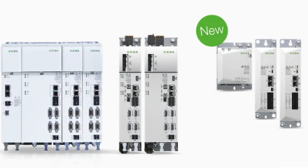
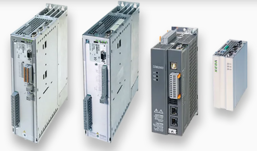
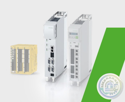
KEBA Servo controllers Flexible, open, intelligent and safe
-
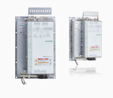
KEBA PitchMaster II+ A Pitch system tailored to your wind turbine installation
-
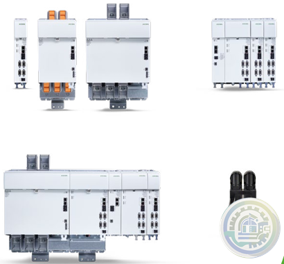
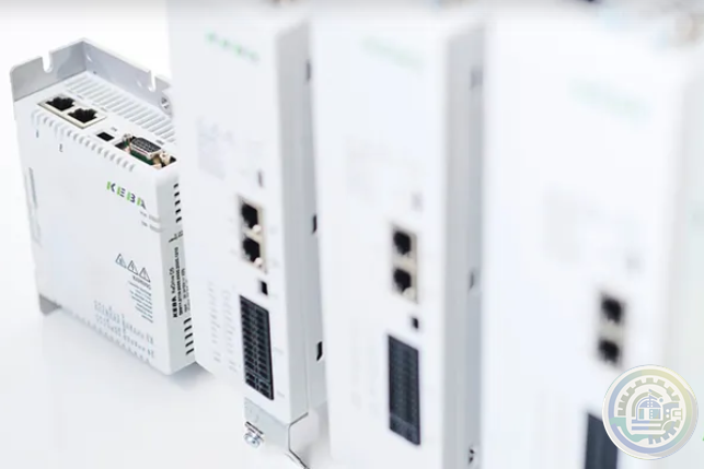
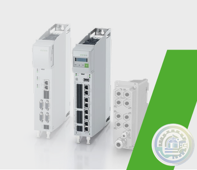
KEBA KeDrive D3 Multi-axis drive system for safe automation solutions
-
KEBA PitchOne System BluePrint
-
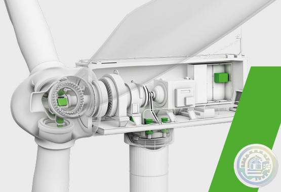
KEBA Pitch motor Sizing and dimensioning
-
KEBA PitchOne (CAM2) Pitch Servo Drives
-
KEBA PitchOne The 5th generation of trailblazing Pitch servo drives
-
KEBA KeDrive D3 System description
-
KEBA c-line Drives Economical positioning inverters
-
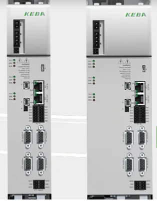
KEBA D3-DA 3xx - axis controllers
-
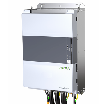
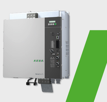
KEBA ServoOne TL 300kW High-Speed Frequency Inverter
-
KEBA ServoOne TL 50 kW High-Speed Frequency Inverter
-
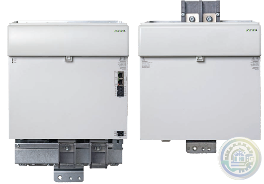
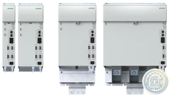
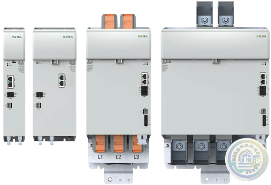
KEBA ServoOne Drive system for safe automation solutions
-
KEBA KeDrive D5 The single-axis controller without compromise
-
KEBA KeDrive D3-AC All-in-one multi-axis drive
-
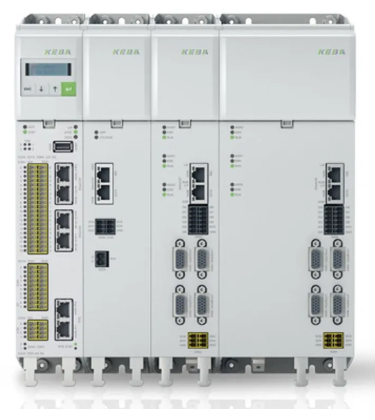
KEBA KeControl C5 A new dimension of flexible expandability
-
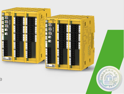
KEBA KeSafe D3-SDC Safe motion monitoring in the drive
-
KEBA KeSafe D3-DU Safe control for robotics & machines
-
KEBA KeSafe C5 Safety Technology
-
KEBA Controlled energy storage system
-
KEBA KeDrive D3-DA axis controller
-
KEBA KeDrive D3-DP 30x supply units
-
KEBA KeDrive D3 Smart DC Systems
-
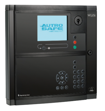
Autronica Maritime gas alarm control panel kit BS-420MG
-
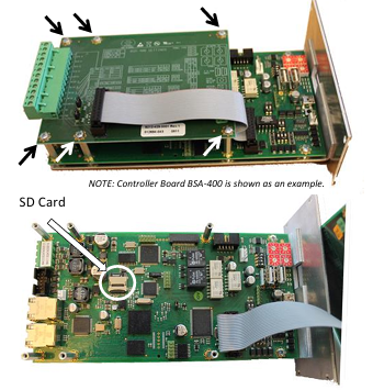
Autronica SD CARD REPLACEMENT IN BC-440, BC-420, BS-420, BS-430 AND BU-BV-420
-
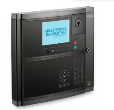
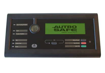
Autronica Operator panel BS-430G2
-
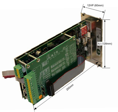
Autronica Controller rack unit BC-440G2
-
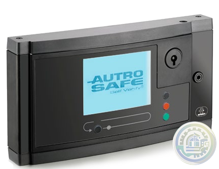
Autronica Controller BC-420G2
-
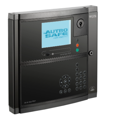
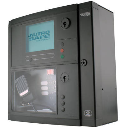
Autronica Fire and gas alarm control panel BS-420G
-
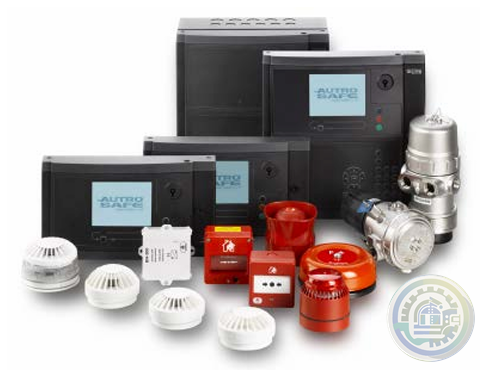
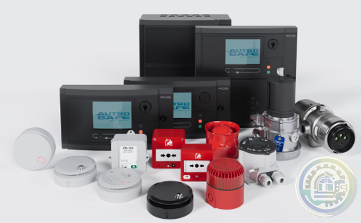
Autronica System Design and Engineering AutroSafe Interactive Fire & Gas Detection System (IFG)
-
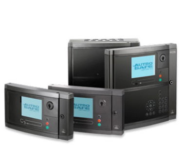
Autronica AutroSafe 4 integrated fire and gas (IFG) panels
-
Autronica AutroSafe Interactive Fire Detection System
-
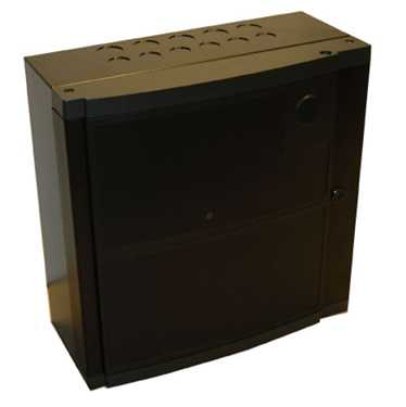
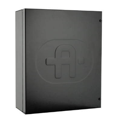
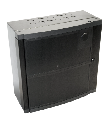
Autronica POWER CABINET BP-405
-
Autronica Fireman panel microphone kit
-
Autronica Fire brigade loop panel BU-110
-
Autronica Information loop panel BV-110
-
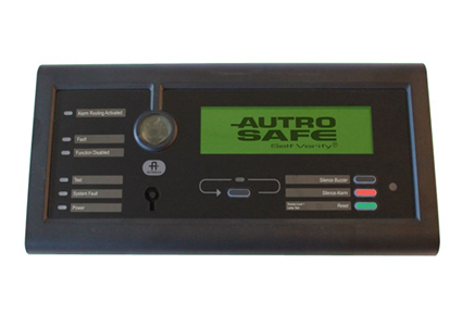
Autronica Repeater Panel BU-BV-420
-
Autronica Operator Panel BS-430
-
Autronica Controller rack unit BC-440
-
Autronica Controller BC-420
-
Autronica MARITIME STD. SOLUTIONS BS-420M (CABINETS AND MOUNTING PLATES)
-
Autronica BRANDALARMCENTRAL BS-420
-
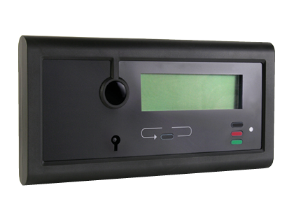
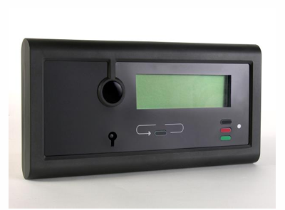
Autronica FIRE ALARM CONTROL PANEL BS-420
-
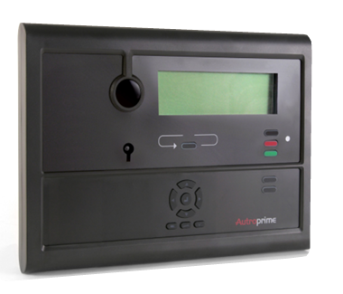
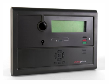
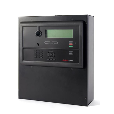
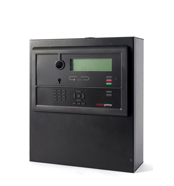
Autronica AUTROPRIME MARITIME FIRE DETECTION UNITS
-
Autronica Mimic cabinet BUR-200, for maritime installations
-
Autronica BUR-200 MIMIKDRIVER
-
Autronica MIMIC DRIVER BUR-200
-
Autronica INFORMATIONSPANEL BV-210
-
Autronica INFORMATION PANEL BV-210
-
Autronica BRANDMANDSPANEL BU-210
- Nidec
- Beckhoff
- Others
- WAGO
- ICS Triplex
- IBA
- Hirschmann
- Bachmann
- Alfa Laval
- Baldor
- Glassman
- Johnson Controls
- Watlow
- ZYGO
- ADVANCED
- KEBA
- Bristol Babcock
- Rolls-Royce
- Aerotech
- Pioneer Magnetics
- Basler
- SAACKE
- BENDER
- Kollmorgen
- MEGGITT
- METSO
- MITSUBISHI
- MTL
- HIMA
- Siemens
- BACHMANN
- AMAT
- DEIF
- DELTATAU
- EATON
- ELAU
- LAM
- SCHNEIDER
- Advantest
- ABB
- GE
- Emerson
- Motorola
- A-B
- KUKA
- Abaco
- HITACHI
- SST
- Vibro-Meter
- Rexroth
- Prosoft
- DFI
- Scanlab
- Reliance
- Parker
- Woodward
- MOOG
- NI
- FOXBORO
- Triconex
- Bently
- ALSTOM
- YOKOGAWA
- B&R
- UNIOP
- KONGSBERG
- Honeywell
- Omron
- CTI
- EPRO


- Tell:+86-18144100983
- email:kongjiangauto@163.com
- Application:wind/ petroleum/ chemical/ natural gas/ Marine/ mining/ aviation/ electronics/ steel/ nuclear power/ electric power/ coking/ air separation and so on
- Series:PLC/ DCS/ servo/ analog/ Ethernet/ digital/ redundant module/ tension system/ excitation/ generator management/ human-machine interface/ detection card/ sensor/ AC drive/ etc
The MicroNet Plus Expansion Chassis may use either single or redundant power supplies.
Each power supply module produces three regulated outputs:
24 V @ 12 A (max), 5 V @ 32 A (max, derated above
55 degree C external ambient temperature), and 5 V Precharge @ 3 A (max).
A motherboard located on the back of the chassis provides the
interconnection of the three outputs from each power supply module
into three corresponding power busses: 24 V bus, 5 V bus, and 5 V precharge bus.
The 24 V and 5 V busses are load shared between the two power supply modules.
The 5 V precharge bus is not load shared.

The power supplies can only be installed into slots PS1 (power supply #1) and PS2 (power supply #2). If
redundant power supplies are not needed, blanking plates must be installed in the slots not being used.
Branch circuit fuses, circuit breakers, and wiring must meet appropriate codes and authorities having
jurisdiction for the specific country (CE, UL, etc.). See Table 4-3 for maximum recommended fuse or
breaker ratings. Do not connect more than one main power supply to any one fuse or circuit breaker. Use
only the wire sizes specified in Table 4-3. which meet local code requirements. Time delay fuses or circuit
breakers must be used to prevent nuisance trips.
Power requirements depend on the number and type of modules supplied for each system. For a system
with a single I/O chassis, size the input power source according to the rating of the MicroNet Plus power
supply to which the source is connected. Do not size the supply mains for the sum of the MicroNet Plus
power supply ratings when redundant supplies are used. MicroNet Plus supplies are redundant when
installed in the same chassis. Redundant supplies share the load between them equally, but each must
provide for full load in the event that one of the units is disabled. Table 4-3 gives the maximum overload
protection for supply mains connected to any single or redundant pair of MicroNet Plus main power
supplies. It is not recommended that both MicroNet Plus main power supplies of a redundant pair be
connected to a single source, since failure of that source would disable the system.
| Woodward | 8273-1013 | 2301E-ST – Steam Turbine Control 8273-1013 | |||
| Woodward | 8273-1014 | 2301E-ST – Steam Turbine Control, Hazardous Location Zone 2 8273-1014 | |||
| Woodward | 8237-2046 | 2301E-HT – Hydro Turbine Control (Francis), 24 VDC, Ordinary Location 8237-2046 | |||
| Woodward | 8200-1400 | 505HT – LVDC, Pelton Turbines 8200-1400 | |||
| Woodward | 8200-1401 | 505HT – HVAC/DC, Pelton Turbines 8200-1401 | |||
| Woodward | 8200-1402 | 505HT – LVDC, Francis / Kaplan Turbines 8200-1402 | |||
| Woodward | 8200-1403 | 505HT – HVAC/DC, Francis / Kaplan Turbines 8200-1403 | |||
| Woodward | 8269-1073 | 17” TouchPanel OCP – Includes RemoteView Software Program 8269-1073 | |||
| Woodward | 8928-5311 | RemoteView - Software License 8928-5311 | |||
| Woodward | 5404-1801 | Old 505 to New 505 Retrofit Wiring Kit 5404-1801 | |||
| Woodward | 8200-1500 | Peak200 – Bulkhead Mount, LV 8200-1500 | |||
| Woodward | 8200-1501 | Peak200 – Bulkhead Mount, HV 8200-1501 | |||
| Woodward | 8200-1502 | Peak200 – Bulkhead Mount, LV, ATEX Zone 2 8200-1502 | |||
| Woodward | 8200-1503 | Peak200 – Front Panel Mount, LV 8200-1503 | |||
| Woodward | 8200-1504 | Peak200 – Front Panel Mount, HV 8200-1504 | |||
| Woodward | 8200-1505 | Peak200 – Front Panel Mount, LV, ATEX Zone 2 8200-1505 | |||
| Woodward | 8200-1508 | Peak200 – Bulkhead Mount, HV, Class1 Div2 Haz. Loc. Compliant 8200-1508 | |||
| User name | Member Level | Quantity | Specification | Purchase Date |
|---|


-
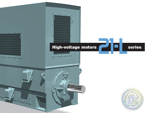 TMEIC High-voltage motors 21-L series
 -
 TMEIC MV Motor & Drive Solutions for Power Generation
 -
 TMEIC AC Motors Rolling Mills
 -
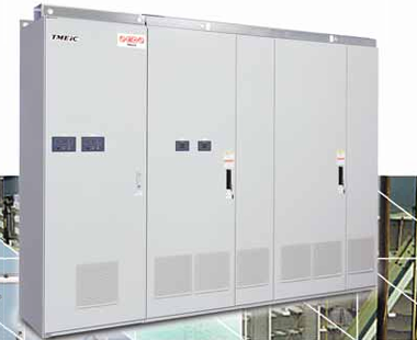 TMEIC TMdrive®-70 Medium Voltage 3-Level IEGT System Drive
 -
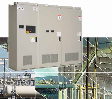 TMEIC TMdrive®-70e2 Medium Voltage 3-Level IEGT System Drive
 -
 TMEIC TMdrive-MVe2 Reactive Power Control
 -
 TMEIC Unified Controller nv Series
 -
 TMEIC TMdrive®-30 Medium Voltage 3-Level IGBT System Drive
 -
 Nidec KBDA Digital AC Drive with CSP™*
 -
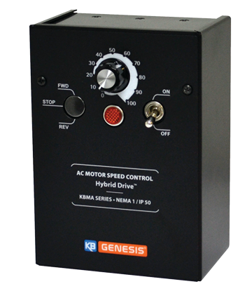 Nidec KBMA Hybrid Drive™ A Digital AC Drive with Analog Interface
 -
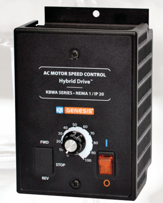 KBWA Hybrid Drive A Digital AC Drive with Analog Interface
 -
 KBVF Hybrid Drive™ A Digital AC Drive with Analog Interface
 -
 Nidec KBVF Micro AC drive
 -
 Nidec Unidrive M608 Industrial general-purpose drive
 -
 Nidec Unidrive M400 General Purpose AC Drives Series
 -
 Nidec Unidrive HS30 General Purpose AC Drives
 -
 Nidec NE200 & NE300 High Performance Vector Control Drives
 -
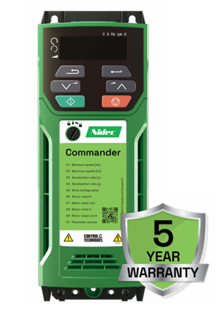 Nidec Commander C Drive
 -
 Nidec Drives Commander S
 -
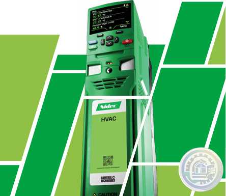 Nidec Drives HVAC Drive H300 Efficiency and reliability in HVAC Specialist Drive
 -
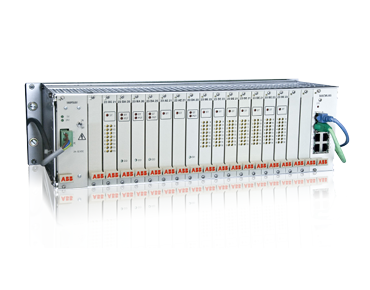 ABB RTU560 product line Reliable solutions for transmission and sub-transmission
 -
 Metso From Ore to Metals: Metso Outotec Offers Complete Solution to Recover Precious & Base Metals from Cengiz Mazidagi
 -
Metso Life Cycle Services for mining
-
 Metso Automation and Analyzer Services Courier® Legacy Upgrade
 -
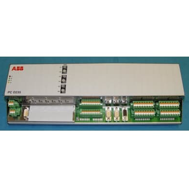 ABB PC D235 A – AC 800PEC CIO-FU Combined Input Output Data Sheet
 -
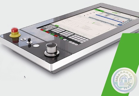 KEBA KeTop AP 524 The stationary, real-time-enabled multitouch panel
 -
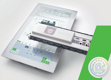 KEBA KePlast i8000 Premium class system for high-end machines
 -
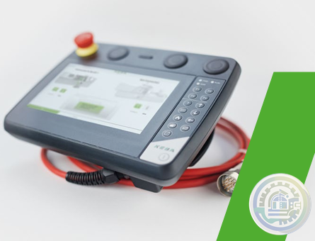 KEBA KeTop T135 Eco The mobile 7" web visualization in the ECO version
 -
 KEBA KeTop T135 The mobile 7" web visualization for all controls
 -
 KEBA KeTop T150/T155 Safe Wireless
 -
 KEBA KeTop T200 The cost-effective replacement for stationary panels
 -
 KEBA KeTop T150 / T155 Handheld terminal
 -
 KEBA KeTop T15x Mobile handheld terminal
 -
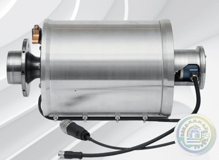 ABB Stressometer® Systems Digital Transmission Unit PFSA107
 -
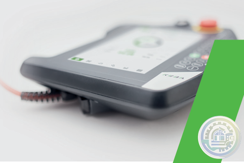 KEBA KeTop T70 Effective mobile operation, brilliant visualization
 -
 KEBA KeTop T10 directMove Operate robots easily and quickly with intuitive gestures
 -
 KEBA KeWheel The adaptive Rotary-Push Button
 -
 KEBA HMI - Human Machine Interface
 -
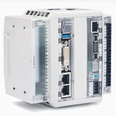 KEBA Module AE 550 Artificial intelligence extension
 -
 KEBA Magnetic bearing drive system LeviTurb
 -
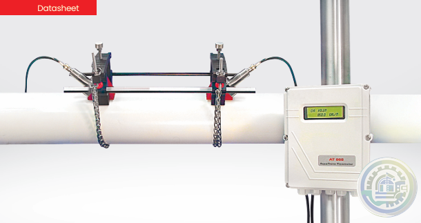 GE AquaTrans™ AT868 Transmetteur de débit liquide à ultrasons Panametrics
 -
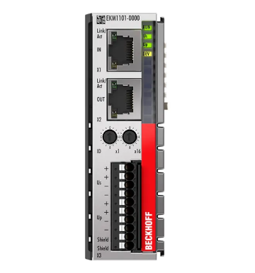 Beckhoff EKM1101 | EtherCAT Coupler with ID switch and diagnostics
 -
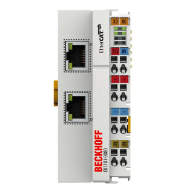 Beckhoff EK1101-0080 | EtherCAT Coupler with ID switch, Fast Hot Connect
 -
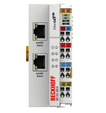 Beckhoff EK1101-0010 | EtherCAT Coupler with ID switch, Extended Distance
 -
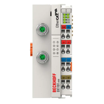 Beckhoff EK1101-0008 | EtherCAT Coupler with ID switch and M8 connection
 -
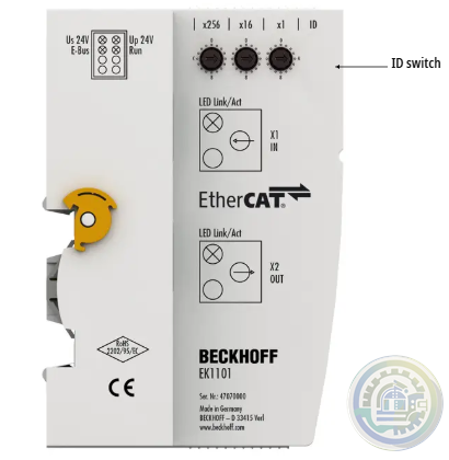 Beckhoff EK1101 | EtherCAT Coupler with ID switch
 -
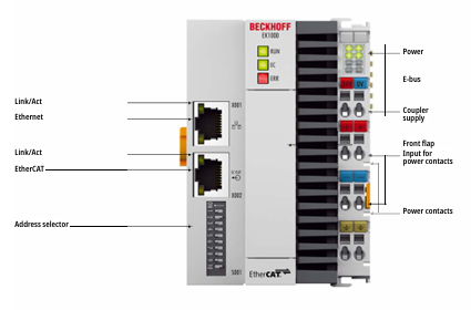 Beckhoff EK1000 | EtherCAT TSN Coupler
 -
 Beckhoff EK1100-0008 | EtherCAT Coupler with M8 connection
 -
 Beckhoff EC1100 | EtherCAT Coupler, RJ45, angled, push-in
 -
 Beckhoff EK1100 | EtherCAT Coupler
 -
 KEBA Servo controllers Flexible, open, intelligent and safe
 -
 KEBA PitchMaster II+ A Pitch system tailored to your wind turbine installation
 -
 KEBA KeDrive D3 Multi-axis drive system for safe automation solutions
 -
 KEBA PitchOne System BluePrint
 -
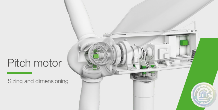 KEBA Pitch motor Sizing and dimensioning
 -
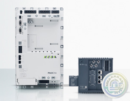 KEBA PitchOne (CAM2) Pitch Servo Drives
 -
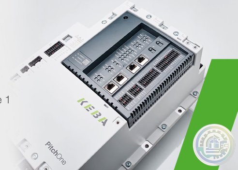 KEBA PitchOne The 5th generation of trailblazing Pitch servo drives
 -
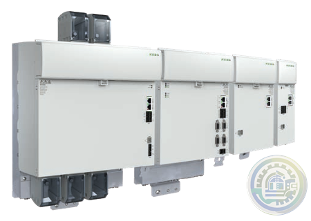 KEBA KeDrive D3 System description
 -
 KEBA c-line Drives Economical positioning inverters
 -
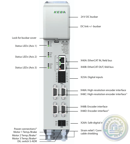 KEBA D3-DA 3xx - axis controllers
 -
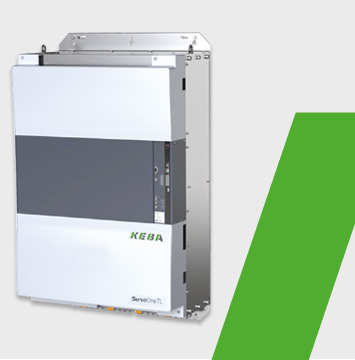 KEBA ServoOne TL 300kW High-Speed Frequency Inverter
 -
 KEBA ServoOne TL 50 kW High-Speed Frequency Inverter
 -
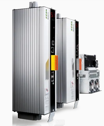 KEBA ServoOne Drive system for safe automation solutions
 -
 KEBA KeDrive D5 The single-axis controller without compromise
 -
 KEBA KeDrive D3-AC All-in-one multi-axis drive
 -
 KEBA KeControl C5 A new dimension of flexible expandability
 -
 KEBA KeSafe D3-SDC Safe motion monitoring in the drive
 -
 KEBA KeSafe D3-DU Safe control for robotics & machines
 -
 KEBA KeSafe C5 Safety Technology
 -
 KEBA Controlled energy storage system
 -
 KEBA KeDrive D3-DA axis controller
 -
 KEBA KeDrive D3-DP 30x supply units
 -
 KEBA KeDrive D3 Smart DC Systems
 -
 Autronica Maritime gas alarm control panel kit BS-420MG
 -
 Autronica SD CARD REPLACEMENT IN BC-440, BC-420, BS-420, BS-430 AND BU-BV-420
 -
 Autronica Operator panel BS-430G2
 -
 Autronica Controller rack unit BC-440G2
 -
 Autronica Controller BC-420G2
 -
 Autronica Fire and gas alarm control panel BS-420G
 -
 Autronica System Design and Engineering AutroSafe Interactive Fire & Gas Detection System (IFG)
 -
 Autronica AutroSafe 4 integrated fire and gas (IFG) panels
 -
 Autronica AutroSafe Interactive Fire Detection System
 -
 Autronica POWER CABINET BP-405
 -
 Autronica Fireman panel microphone kit
 -
 Autronica Fire brigade loop panel BU-110
 -
 Autronica Information loop panel BV-110
 -
 Autronica Repeater Panel BU-BV-420
 -
Autronica Operator Panel BS-430
-
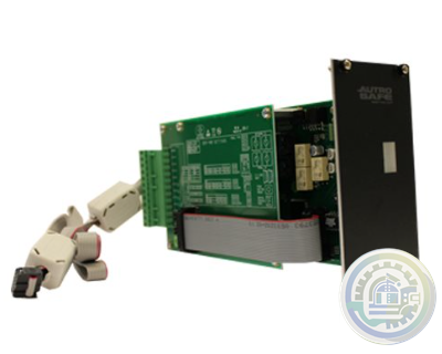 Autronica Controller rack unit BC-440
 -
 Autronica Controller BC-420
 -
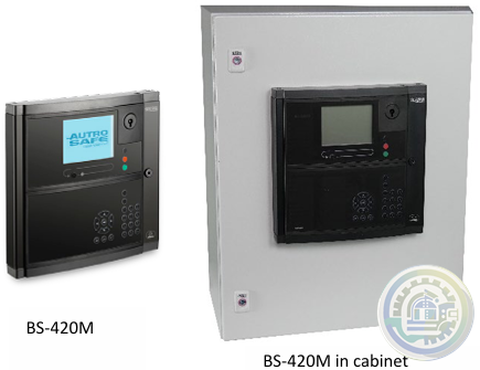 Autronica MARITIME STD. SOLUTIONS BS-420M (CABINETS AND MOUNTING PLATES)
 -
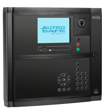 Autronica BRANDALARMCENTRAL BS-420
 -
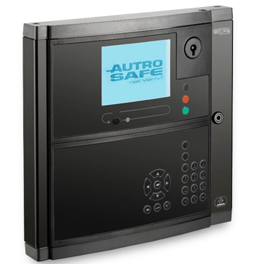 Autronica FIRE ALARM CONTROL PANEL BS-420
 -
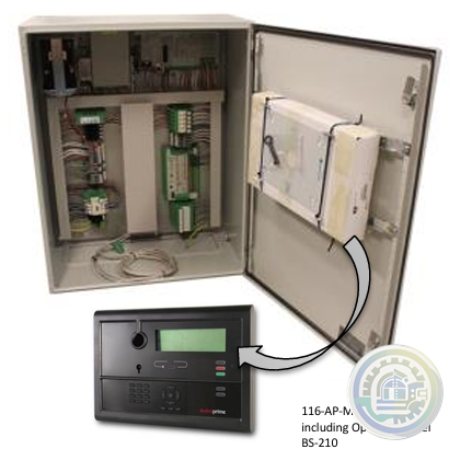 Autronica AUTROPRIME MARITIME FIRE DETECTION UNITS
 -
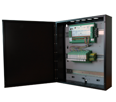 Autronica Mimic cabinet BUR-200, for maritime installations
 -
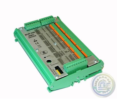 Autronica BUR-200 MIMIKDRIVER
 -
Autronica MIMIC DRIVER BUR-200
-
 Autronica INFORMATIONSPANEL BV-210
 -
 Autronica INFORMATION PANEL BV-210
 -
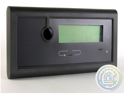
 Autronica BRANDMANDSPANEL BU-210
 -
 Autronica FIRE BRIGADE PANEL BU-210
 -
 Autronica REPEATERPANEL BS-211
 -
 Autronica BS-211 REPEATER PANEL
 -
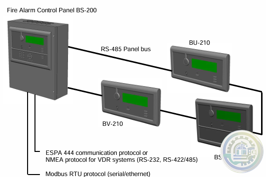
 Autronica BS-200M FIRE ALARM CONTROL PANEL
 -
 Autronica BRANDALARMCENTRAL BS-200
 -
Autronica FIRE ALARM CONTROL PANEL - BS-200
-
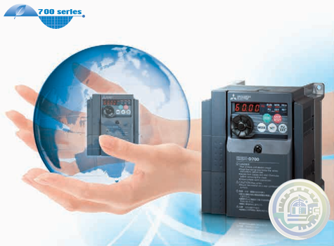 MITSUBISHI ELECTRIC INVERTER FR-D700 Global standard
 -
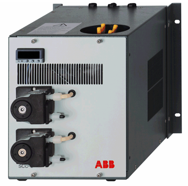 ABB SCC-C Sample gas cooler
 -
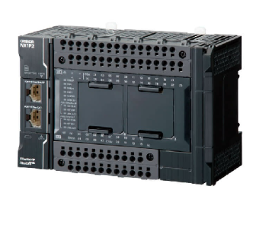 Omron NX1P Machine Automation Controller
 -
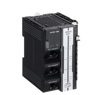 Omron NX102 Machine Automation Controller
 -
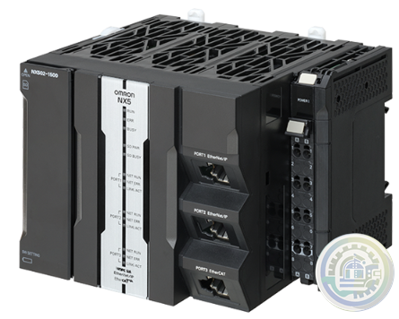 Omron NX502 Machine Automation Controller
 -
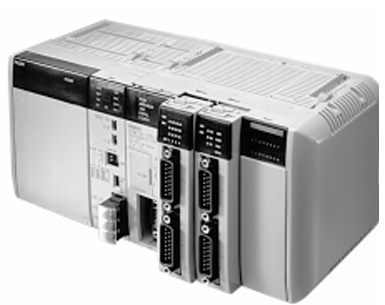 Omron CQM1H Programmable Controller
 -
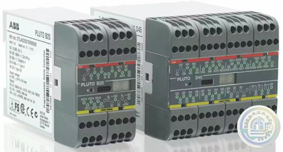 ABB Pluto Safety PLC A compact, powerful and user-friendly safety PLC.
 -
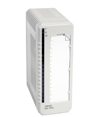 AI830A ABB Ability™ System 800xA® hardware selector
 -
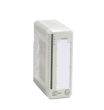 ABB AO895 3BSC0690087R1 Analog Output IS HART 8 ch
 -
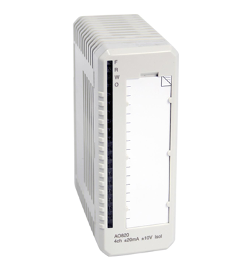 ABB AO820 System 800xA hardware selector
 -
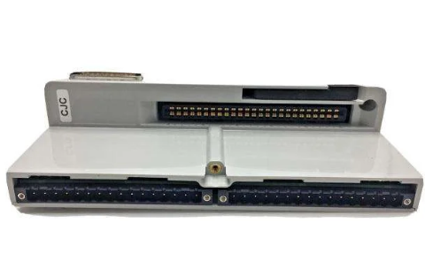 ABB HBS01-CJC I/O MTUs - SD Series I/O
 -
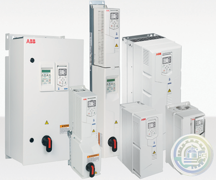 ABB drives for HVAC ACH550 to ACH580 comparison guide
 -
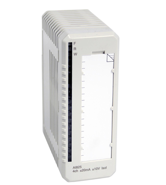 ABB AI825 System 800xA hardware selector
 -
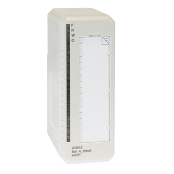 ABB AO815 System 800xA hardware selector
 -
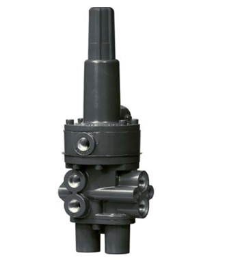 Emerson Fisher™ 377 Trip Valve
 -
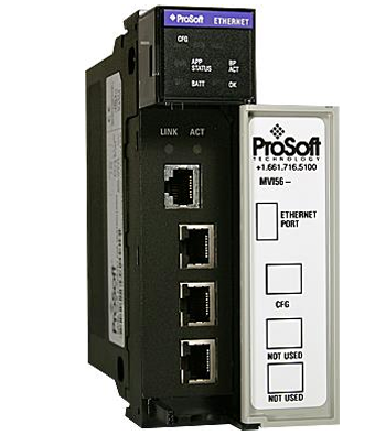 Prosoft MVI56-104S IEC 60870-5-104 Ethernet Server Communication Module with Edition 2 Support
 -
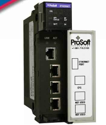 Prosoft MVI56-EGD GE Ethernet Global Data Communication Module
 -
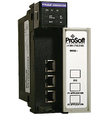 Prosoft MVI56-LTQ Limitorque Valve Actuator Master Communication Module
 -
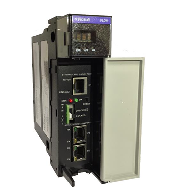 Prosoft MVI56E-AFC Enhanced Liquid & Gas Flow Computer for ControlLogix®
 -
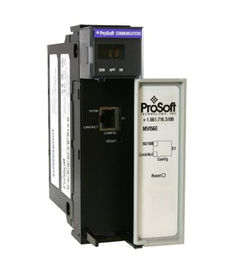 Prosoft MVI56E-GEC Generic ASCII Ethernet Communication Module
 -
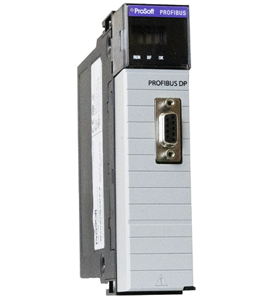 Prosoft ILX56-PBM PROFIBUS DPV1 Master/Slave for ControlLogix®
 -
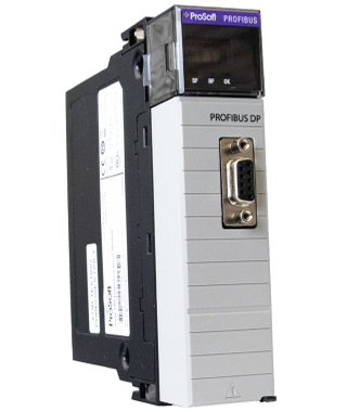 Prosoft ILX56-PBS PROFIBUS DPV1 Slave for ControlLogix®
Please do not listen to the advice of non-professional engineers! Cause equipment damage!


wechat/whatsapp:
+86-181-44100-983
Email: kongjiangauto@163.com
-
ABB 3BUS208720-001 POWER SIGNAL INTERCONNECT
-
ABB AC 800PEC CIO-FU PC D235 A101 3BHE032025R0101 Combined Input Output
-
ABB PFSA240 Roll DC Supply Unit 3BSE073476R1
-
ABB PFSA107-Z42 DTU Stressometer Digital Transmission Unit
-
GE AT868-2-1-1 Panametrics Ultrasonic Liquid Flow Transmitter
Copyright © 2009 - 2024 Cld , All Rights Reserved K-JIANG All rights reserved