-
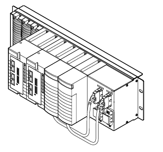
Kollmorgen AKT2G-AC-FAN-001 fan cartridge
-
Kollmorgen AKT-AN-820-000 8-Channel Analog Input Terminal
-
Kollmorgen 4-Channel Analog Input Terminal (AKT-AN-420-000)
-
METSO D201379 PC Board PLC & ADD-ON Board
-
Metso PDP403 Distributed Processing Unit
-
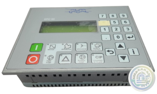
Alfa Laval EPC 60 Retrofit kit
-
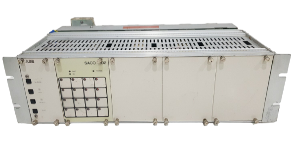
ABB Digital annunciator unit SACO 64D4
-
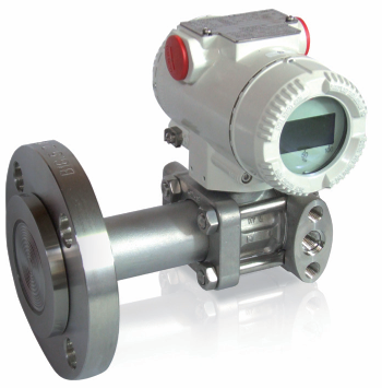
ABB Model 264DD Differential/Gauge
-
ABB Alarm annunciators
-
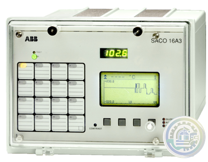
ABB SACO 16 A3 Analog Annunciator Unit
-
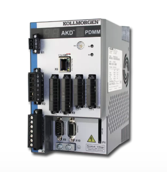
Kollmorgen AKD PDMM® Programmable Drive, Multi-Axis Master
-
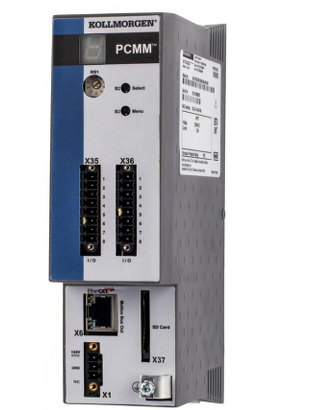
Kollmorgen PCMM: Programmable Controller, Multi-Axis Master
-
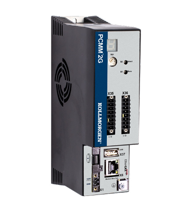
Kollmorgen PCMM2G: Next-Generation Performance in a Powerful, Compact Controller
-
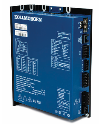
Kollmorgen P80630 Stepper Drive
-
Kongsberg Maritime System and vessel conversions
-
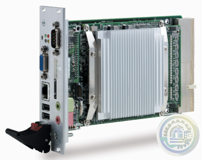
ADLINK CPCI-3840 3U CompactPCI Intel® Pentium® M Processor Module
-
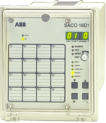
ABB Digital Annunciator Unit SACO 16D1
-
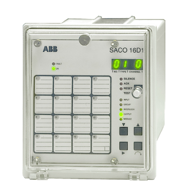
ABB SACO16D1-AA Digital Annunciator Unit
-
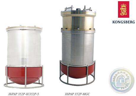
Kongsberg HIPAP® 352P PORTABLE HIGH PRESICION ACOUSTIC POSITIONING
-
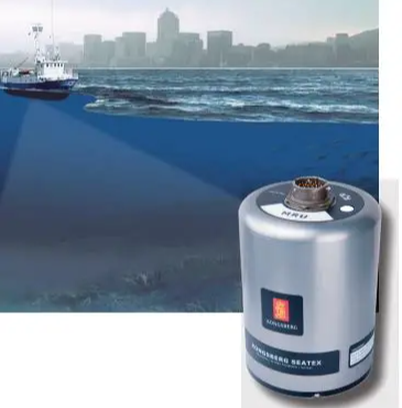
Kongsberg MRU 5 Motion Reference Unit
-
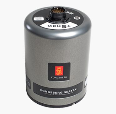
Kongsberg MRU 5+ Motion Reference Unit
-
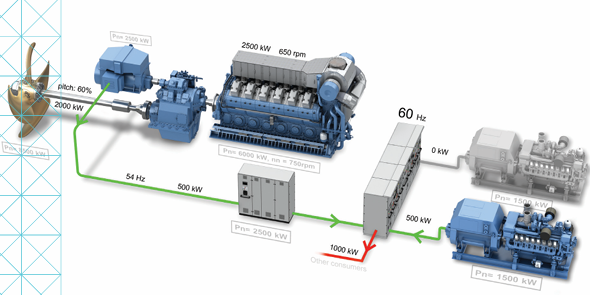
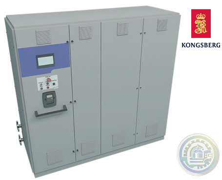
Kongsberg KONGSBERG MARITIME PROPULSION SYSTEMS Active Front End (AFE)
-
Kongsberg HiPAP 352P Portable acoustic positioning system
-
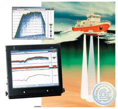
Kongsberg EA600 New generation precision hydrographic echo sounder
-
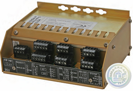
Kongsberg Digital Governor Unit (DGU) AutoChief® 600
-
Kongsberg AutoChief® 600 Propulsion Control System
-
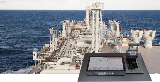
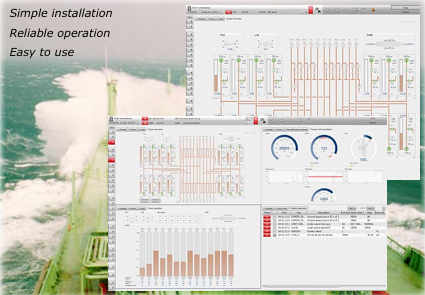
Kongsberg K-Chief Vessel Automation System
-
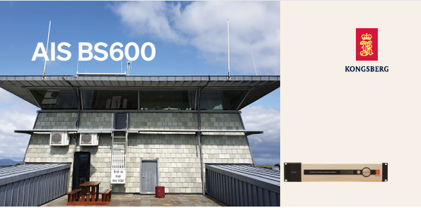
Kongsberg AIS BS600 Automatic Identification System - Base Station
-
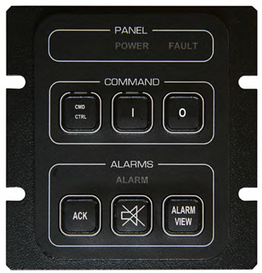
Kongsberg K-Chief 600 Alarm and Command Panel
-
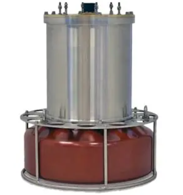
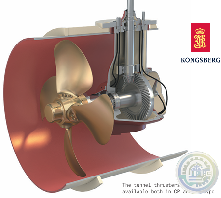
Kongsberg Tunnel Thrusters Type TT FP
-
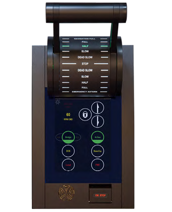
Kongsberg AutoChief®600 Lever Telegraph Unit (LTU11)
-
YOKOGAWA Model AW810D Wide Area Communication Router
-
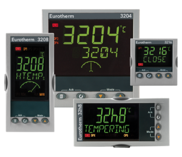
Watlow Eurotherm® 3200 Temperature/Process Controller
-
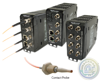
Watlow EtherCAT®, Fiber Optic Temperature Measurement and Control System
-
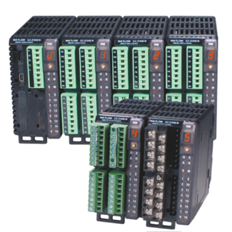
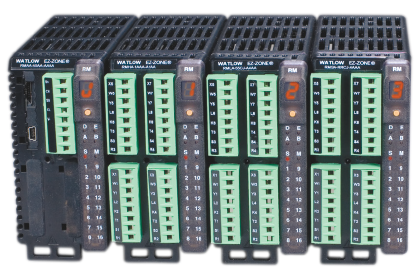
Watlow EZ-ZONE® RM Modular Controller Family
-
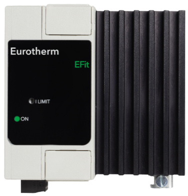
Watlow EFit SCR Power Controller
-
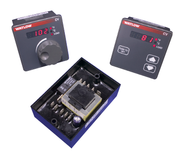
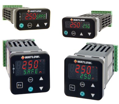
Watlow Basic Temperature and Limit Controllers
-
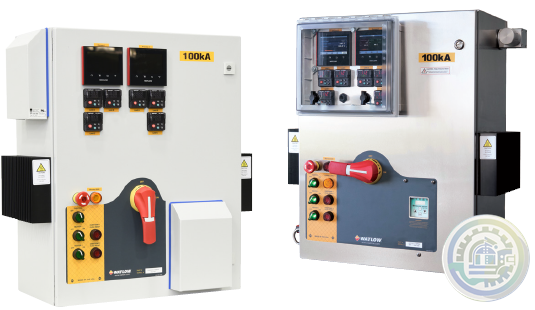
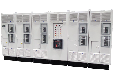
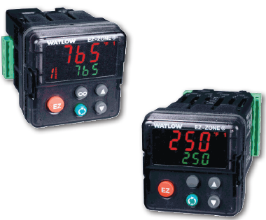
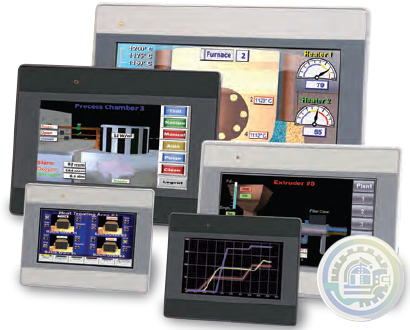
Watlow’s New WATCONNECT® Control Panels
-
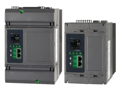
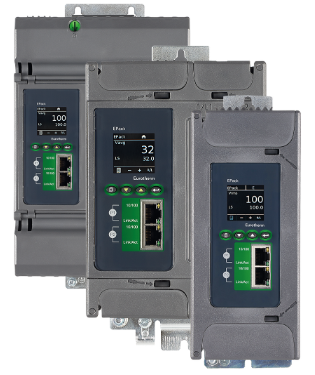
Watlow EPack-2PH Compact SCR Power Controllers
-
Watlow Large and Extra-Large WATCONNECT® Panels
-
Watlow Eurotherm® EPack™ compact SCR power controllers-1PH -2PH -3PH
-
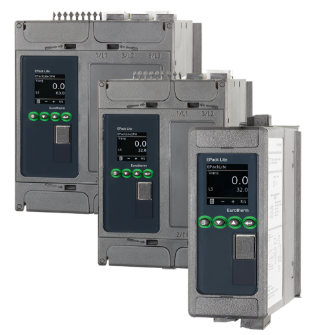
Watlow Eurotherm® EPack™ Lite Compact SCR Power Controllers
-
Watlow EPack™ Lite-1PH Compact SCR Power Controllers
-
Watlow’s new SERIES LS offers fixed limit set point temperature values
-
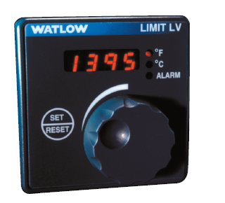
Watlow The SERIES LV limit family
-
Watlow’s family of microprocessor- based limit controllers SERIES LF
-
Watlow The EZ-ZONE RM controller simplifies thermal system management
-
Watlow The PM LEGACY™ series panel mount controller
-
Watlow EZ-ZONE® Remote User Interface (RUI)
-
Watlow Silver Series EM Operator Interface Terminal
-
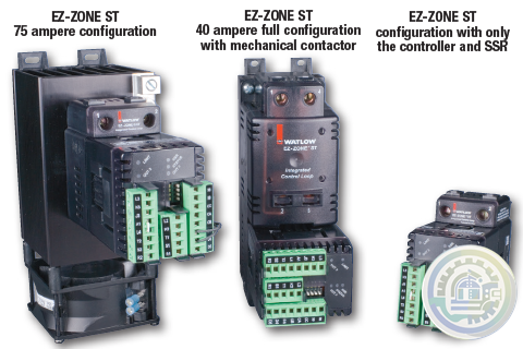
The EZ-ZONE® ST integrated solid state controller from Watlow®
-
YOKOGAWA Cooling Water Pump Failure Prediction Monitoring
-
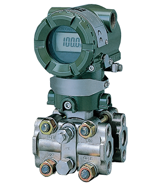
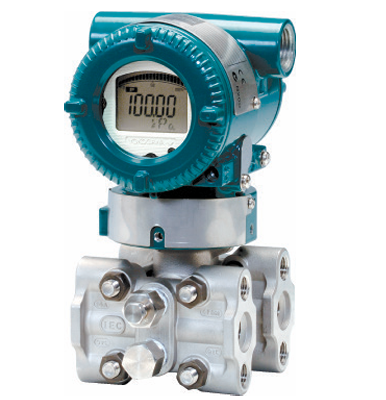
YOKOGAWA EJA Series Differential Pressure and Pressure Transmitters
-
YOKOGAWA EJA110E Diff erential Pressure Transmitter
-
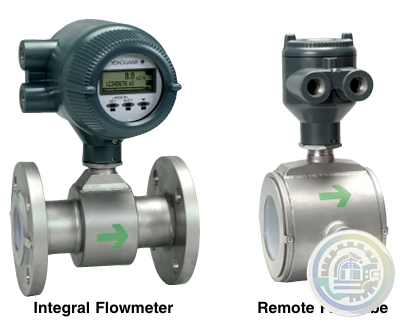
YOKOGAWA AXF Magnetic Flowmeter Series
-
YOKOGAWA Turbomachinery Controller Overview (FCN-500/FCN-RTU)
-
YOKOGAWA STARDOM FCN-RTU Autonomous Controller
-
YOKOGAWA FCN Autonomous Controller Hardware (FCN-100)
-
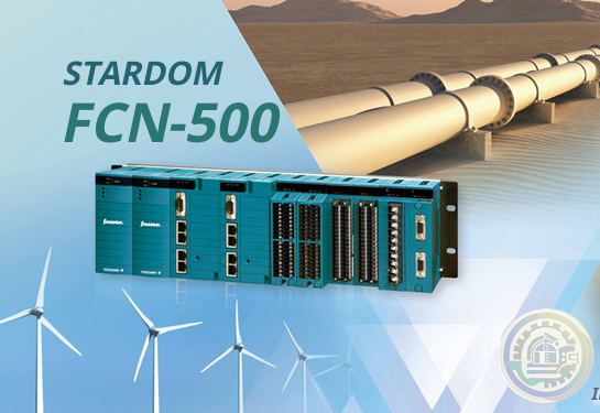
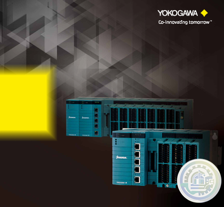
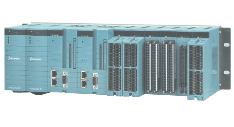
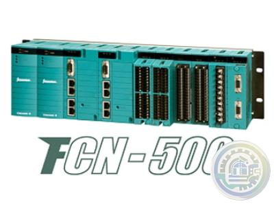
YOKOGAWA STARDOM FCN-500 Autonomous Controller
-
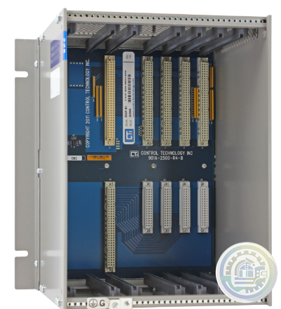
CTI 2500-R4 Four-Slot Base with High-Speed Channel
-
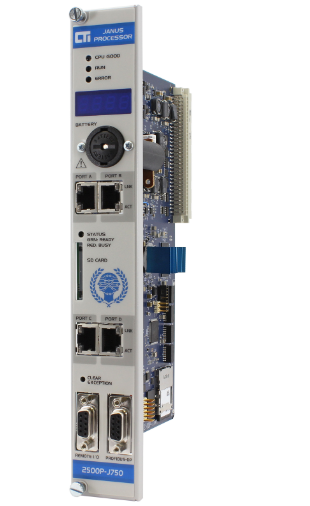
CTI 2500P-J750 Janus PAC with 3MB Project Memory
-
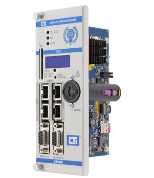
CTI 2500C-J750“Janus”Compact Programmable Automation Controller
-
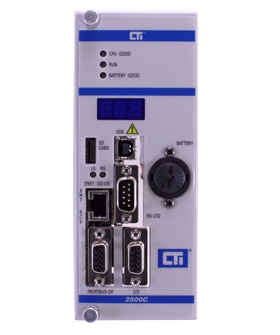
CTI 2500 Series® Compact Programmable Controllers
-
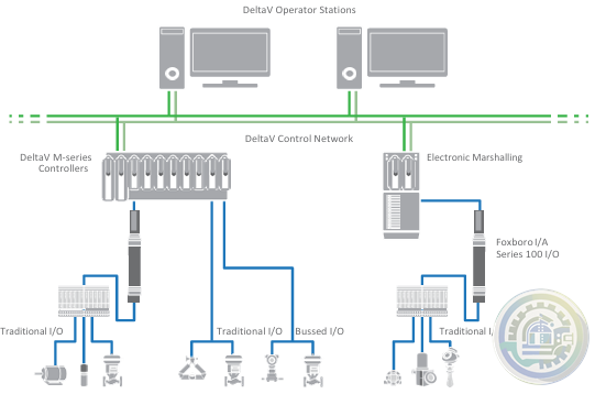
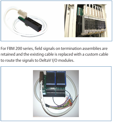
Emerson DeltaV™ Flex.Connect Solutions for Foxboro™ I/A Series 100 I/O
-
Emerson Modernization of Foxboro I/A Series® Systems to the DeltaV™ System
-
Foxboro DCS Fieldbus Modules for APACS+™ Automation Systems
-
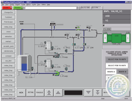
Foxboro Evo™ Process Automation System
-
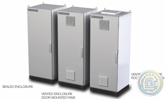
Foxboro™ DCS G61 Tricon Termination Enclosure
-
Foxboro G60 Tricon System Enclosure I/A Series® HARDWARE
-
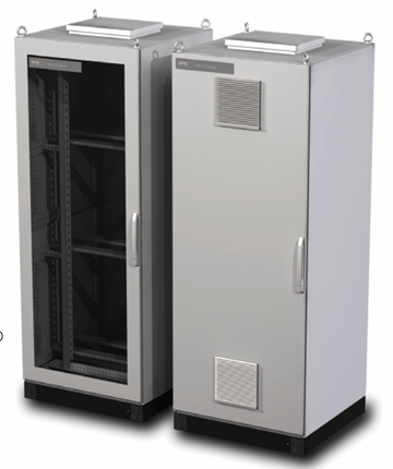
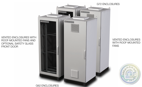
Foxboro G62 and G72 Tricon System and Termination Enclosures
-
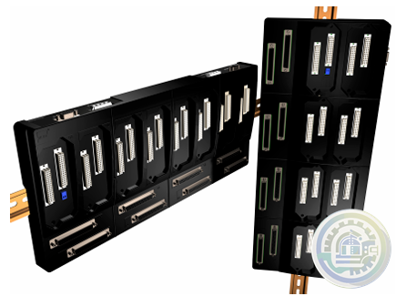
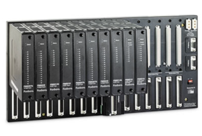
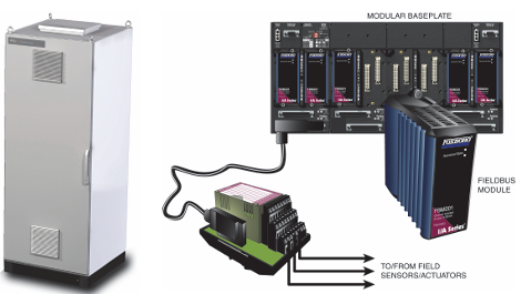
Foxboro I/A Series® Hardware DIN Rail Mounted Fieldbus Module Baseplate
-
Kongsberg K-Chief 600 Marine automation system
-
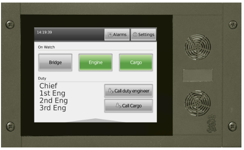
Kongsberg WCC 600 Watch Call Panels
-
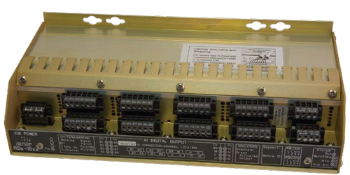
Kongsberg Distributed Processing Units Remote Digital Output (RDo-16xe)
-
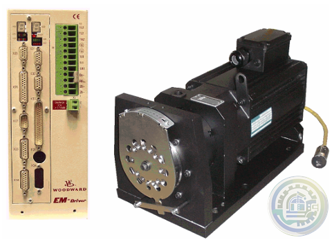
Woodward EM‐80 and EM‐300 Actuators All‐Electric Actuator System
-
Foxboro DCS FBM for Migration of Bailey® Systems
-
Foxboro Migration with FCP280 and DCS FBMs
-
Foxboro DCS Fieldbus Modules for Siemens APACS+™ Automation Systems
-
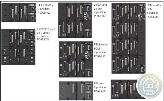
Foxboro 200 Series Baseplate Module Mounting
-
Foxboro Standard 200 Series Subsystem Overview
-
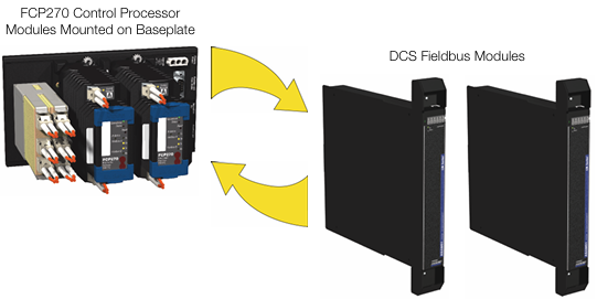
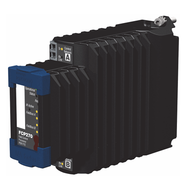
Foxboro Field Control Processor 270 (FCP270)
-
Johnson Controls DIS1710 Local Controller Display Installation Instructions
-
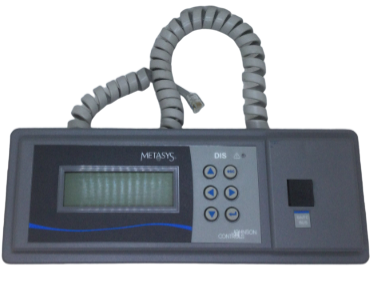
Johnson Controls FX-DIS Local Controller Display
-
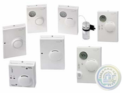
Johnson Controls WRZ Series Wireless Room Sensors
-
Woodward EM-80/EM-300 Actuator System
-
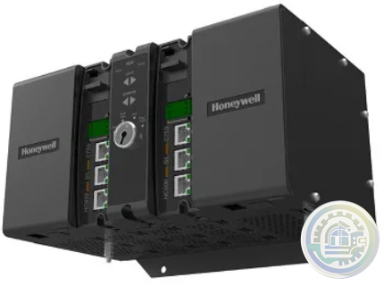
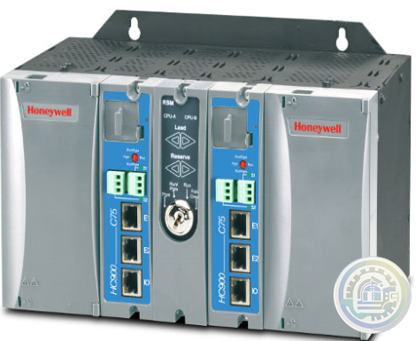
Honeywell ControlEdge™ PLC Modular Controllers
-
Honeywell CONTROLEDGE PCD Compact, Cyber Secure Control System
-
Honeywell M6410A, M7410F Non-Spring Return Cartridge Globe Valve Actuator
-
Honeywell ControlEdge™ HC900 How Does It Work?
-
Honeywell ControlEdge HC900 controller
-
Honeywell HC900 Functional Overview
-
Honeywell Optimizer Advanced Controllers are a family of next generation integration & plant controllers
-
Honeywell Optimizer Advanced Controller
-
Honeywell Excel Web II Control System
-
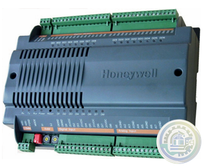
Honeywell CPO-PLANT Controller area of the site
-
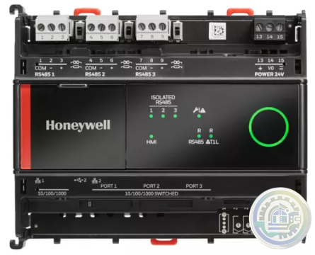
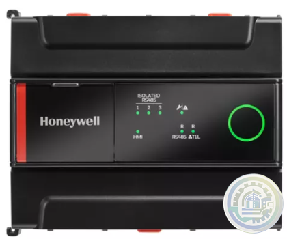
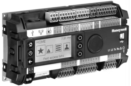
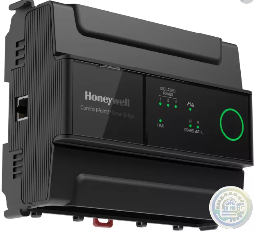
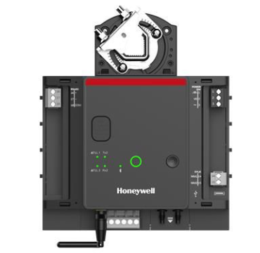
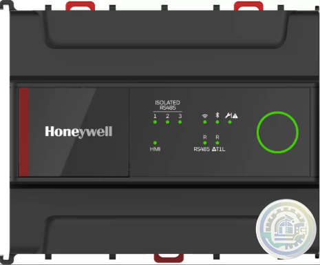
Honeywell ComfortPoint Niagara T1L VAV Controller
-
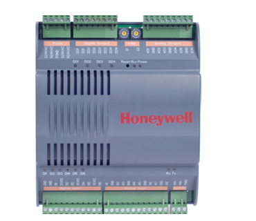
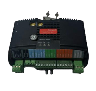
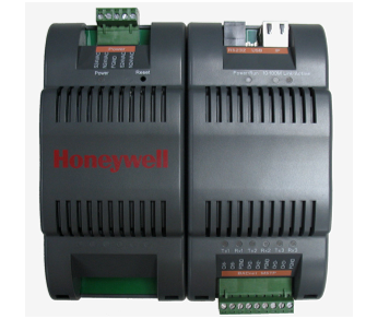
Honeywell ComfortPoint™ Open Plant Controller
-
Honeywell ComfortPoint Open CP-EXPIO (EXPANSION IO BOARD)
-
Honeywell ComfortPoint Open CPO-VAV2A-US (UNITARY CONTROLLER)
-
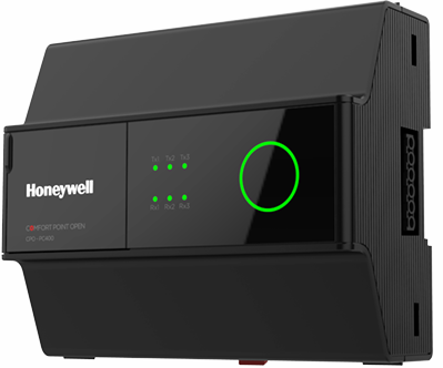
Honeywell ComfortPoint™ Open CPO-PC400 Plant Controller
-
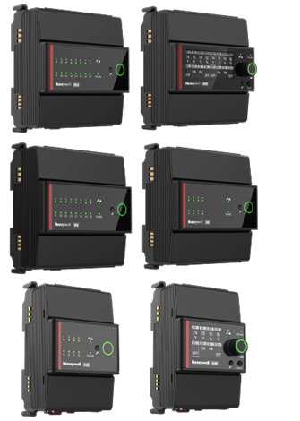
Honeywell I/O MODULES EXPANSION MODULES & WIRING ADAPTER
-
Honeywell CPO-DIO ComfortPoint Open (DIGITAL I/O CONTROLLER)
-
Honeywell CP-Core ComfortPoint Open
-
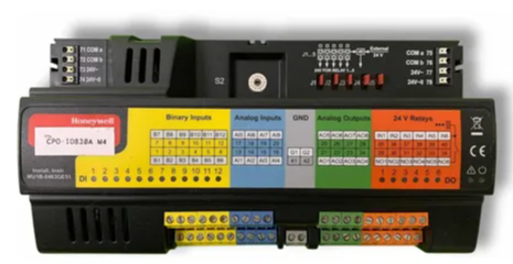
Honeywell CPO-IO830A ComfortPoint Open MIXED I/O MODULE
-
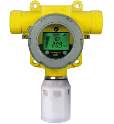
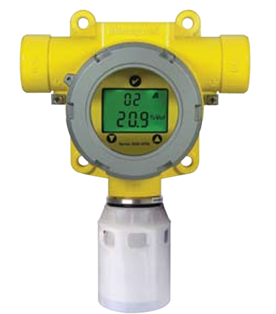
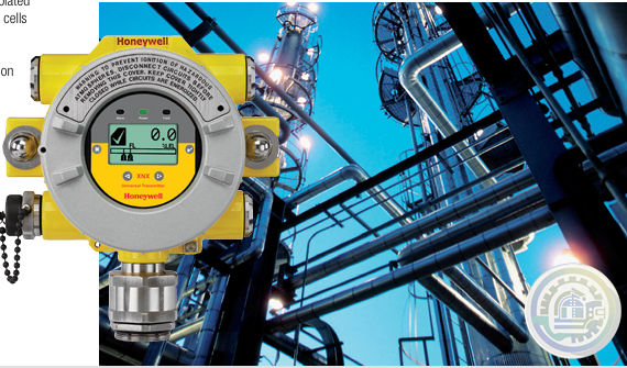
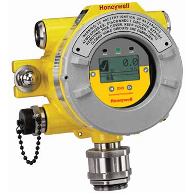
Honeywell Sensepoint XCD
- Baldor
- Glassman
- Johnson Controls
- Studer
- Watlow
- AEG
- ADVANCED
- KEBA
- Bristol Babcock
- Rolls-Royce
- Aerotech
- APPLIED MATERIALS
- Basler
- SAACKE
- BENDER
- Kollmorgen
- MEGGITT
- METSO
- MITSUBISHI
- MTL
- HIMA
- Siemens
- BACHMANN
- AMAT
- DEIF
- DELTATAU
- EATON
- ELAU
- LAM
- SCHNEIDER
- Advantest
- ABB
- GE
- Emerson
- Motorola
- A-B
- KUKA
- Abaco
- HITACHI
- SST
- Vibro-Meter
- Rexroth
- Prosoft
- DFI
- Scanlab
- Reliance
- Parker
- Woodward
- MOOG
- NI
- FOXBORO
- Triconex
- Bently
- ALSTOM
- YOKOGAWA
- B&R
- UNIOP
- KONGSBERG
- Honeywell
- Omron
- CTI
- EPRO
- Tell:+86-18144100983
- email:kongjiangauto@163.com
- Application:wind/ petroleum/ chemical/ natural gas/ Marine/ mining/ aviation/ electronics/ steel/ nuclear power/ electric power/ coking/ air separation and so on
- Series:PLC/ DCS/ servo/ analog/ Ethernet/ digital/ redundant module/ tension system/ excitation/ generator management/ human-machine interface/ detection card/ sensor/ AC drive/ etc
In a system where the field wiring is required to be connected to the
rear of the system, the rack is centrally divided into front and rear
sections by a printed circuit board backplane which provides common
power and signal routeing between individual Channel Control Cards.
Channel Control Cards are fitted at the front of the rack while Interface/
Relay cards are fitted directly behind the Channel Control Cards at the
rear of the rack. The Channel Control Cards and their respective
Interface/Relay Cards are interconnected by a plug and socket arrangement.


In a system where the field wiring is required to be connected to the
front of a system, the Channel Control Cards and Interface/Relay
Cards are mounted one above the other in a 6U rack. The backplane
printed circuit board still provides the common power and signal
routeing between the individual Channel Control Cards while short
cables at the rear of the cards connect each Channel Control Card to
their respective Interface/Relay Card.
Simple calibration and checking of the system is carried out using
push buttons on the Engineering Card fitted to each rack. More
complex configuration can be carried out using the RS232 link between
the Engineering Card and an external IBM compatible personal
computer running the engineering interface software.
Additional functions can be provided by the Engineering Card using
optional modules that plug into the Engineering Card. See the following
module operating instruction manuals:
05701M5006 Modbus Interface Module
05701M5007 Event Printing Module
05701M5008 Master Alarm Update Module
The 5701 Control System is shown in Figure 1 with an overview at Figure 2.

General
The power converter modules DCS800-S have the protection class IP00 and are to be mounted in a cubicle or finger protected area.
There are different sizes (D1. D2. D3. D4. D5. D6. D7), graduated in terms of current and voltage ranges.
All units are equipped with the DCS800 Control Panel.
It can be snapped into place on the power converter module or installed in the switchgear cubicle door by means of amounting kit.
Accessories such as external fuses, line reactors etc. are also available, to complete the drive system.
All converter modules up to 525 V and 1000 A (D1...D4) are equipped with field exciters.
The power section of the converters is available as single (2-Q) bridge or double (4-Q) bridge. 4-Q drives are required for regenerative breaking.
4-Q drives can be built by:
–Double (4-Q) armature bridge or –Single (2-Q) armature bridge plus a double (4-Q) field converter bridge
The bridge type has an influence on the maximum output voltage of the converter. See table below.
CONSTRUCTION
The system consists of individual 1'' (2.54cm) wide cards fitted to a
rigid custom rack designed to fit Euro rack cabinets. Two rack widths
are available:
a. 19 inch with 17 card slots to house up to 16 Channel Control Cards
and an Engineering Card.
b. Half 19 inch with nine card slots to house up to eight Channel
Control Cards and an Engineering Card.
Each sub-rack contains an Engineering Card and a DC Input Card to
make up the rack system
The system is designed to meet the differing customer wiring
configurations and to achieve this the control functions are split away
from the relays and field wiring connections. A single channel of gas
detection therefore consists of:
a. Sensor Drive Module
In order to achieve compatibility with a range of different inputs and
sensor types, the circuitry necessary to control the sensor is
housed on an independent plug-in Sensor Drive Module. These
modules plug directly into a Channel Control Card and are factory
fitted. There are two different modules, one for catalytic inputs and
one for 4 - 20mA inputs.
b. Single Channel Control Card
Each Single Channel Control Card functions independently and
contains all the necessary electronic circuitry to provide the sensor
drive, alarm detection and gas level display for that channel of gas
detection.
c. Field Interface or Relay Card
The Field Interface/Relay Cards provide the interface connections
between the Control Cards and their respective field connected
gas sensor. In addition, Relay Cards provide alarm outputs to the
field connections.

Other advantageous products on sale are listed below:
Honeywell 05704-A-0121 Four relay interface card
ABB VBS01-CJC Vert. Base Single Cold Junction Comp.
ABB VBS01-CJCA Vert. Base Single Cold Junction Comp.
ABB VBS01-EPD Vert. Base Single Ext. Pwr Inputs
Digital Input (125 VAC/VDC Indiv. Fused) )1C31232G03 5X00034G01
Digital Input (125 VAC/VDC differential) 1C31232G03
Digital Input (24/48 VAC/VDC Indiv. Fused) 1C31232G02 5X00034G01
Honeywell 05704-A-0145 Control card 4-20mA
Honeywell 05704-a-0144 Four channel control card
Honeywell 05704-c-0160 Catalysis Interconnect
Honeywell 04200-A-0146 Analog output module source
Honeywell 04200-A-0145 Analog output module receiver
ABB VBX01B HN800 Bus Extender Vertical Bottom
ABB VBX01BA HN800 Bus Extender Vertical Bottom
ABB VBX01K02 HN800 Bus Extender Kit Vertical
ABB VBX01K02A HN800 Bus Extender Kit Vertical
ABB VBX01T HN800 Bus Extender Vertical Top
ABB VBS01-EPDA Vert. Base Single Ext. Pwr Inputs
ABB VBS01-FPH Vert. Base Single Field Pwr Hot
ABB VBS01-FPHA Vert. Base Single Field Pwr Hot
ABB VBS01-FPN Vert. Base Single Field Pwr Neutral
ABB VBS01-FPNA Vert. Base Single Field Pwr Neutral
Honeywell 05701-A-0515 Front entrance 16-way splitter
Honeywell 05701-C-0390 Interconnecting Cable
Honeywell 05701-A-0365 Blanking Panel
Honeywell 05701-A-0351 Control Card
Honeywell 05701-A-0283 4 - 20mA Sensor Drive
Contact Input w/Onboard 48 V wetting 1C31142G01 1C31110G03
Digital Input (125 VAC/VDC differential) 1C31107G02 1C31110G02
Digital Input (125 VAC/VDC single ended) 1C31107G02 1C31110G01
Honeywell 05701-A-0284 Catalytic Sensor Drive
Honeywell 05701-A-0326 Field Interface Card
Honeywell 05701-A-0327 Double SPCO Relay Card
Honeywell 05701-A-0328 Triple SPCO Relay Card
Honeywell 05701-A-0329 Triple DPCO Relay Card
Honeywell 05701-A-0330 High Integrity Relay Card
Digital Input (24 VAC/VDC or 48 VDCdifferential) 1C31107G01 1C31110G02
Digital Input (24 VAC/VDC or 48 VDC singleended) 1C31107G01 1C31110G01
| User name | Member Level | Quantity | Specification | Purchase Date |
|---|


Please do not listen to the advice of non-professional engineers! Cause equipment damage!


wechat/whatsapp:
Email: kongjiangauto@163.com
-
Vibro-meter vmf-RLC16-V111 200-570-101-015 200-570-000-111 Relay Card
-
Vibro-meter vmf-IOC4T 200560-101-017 200-560-000-111 I/O module
-
vmf cpum vmf-cmc16 200-530-111-013 200-530-100-014 Vibro-meter Monitoring system Modulee
-
Vibro-meter 200-595-045-114 | CPUM | Vibration Processor Module
-
Vibro-meter SIM-275A 200-582-500-013 state-of-the-art protection and monitoring module
Copyright © 2009 - 2024 Cld , All Rights Reserved K-JIANG All rights reserved


