-
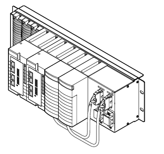
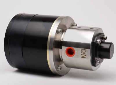
Kollmorgen AKT2G-AC-FAN-001 fan cartridge
-
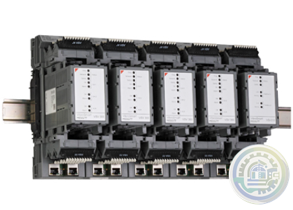
Kollmorgen AKT-AN-820-000 8-Channel Analog Input Terminal
-
Kollmorgen 4-Channel Analog Input Terminal (AKT-AN-420-000)
-
METSO D201379 PC Board PLC & ADD-ON Board
-
Metso PDP403 Distributed Processing Unit
-
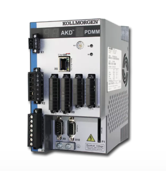
Kollmorgen AKD PDMM® Programmable Drive, Multi-Axis Master
-
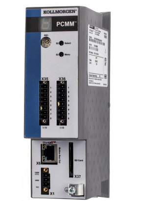
Kollmorgen PCMM: Programmable Controller, Multi-Axis Master
-
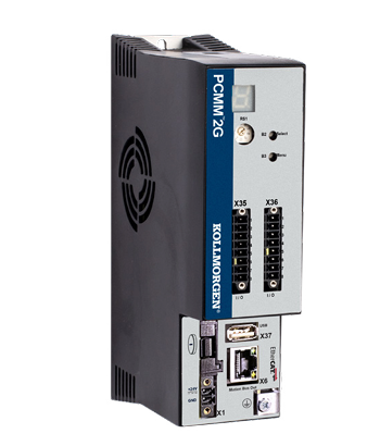
Kollmorgen PCMM2G: Next-Generation Performance in a Powerful, Compact Controller
-
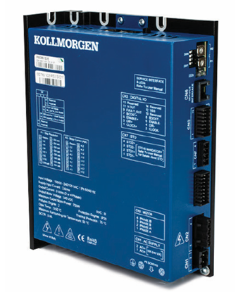
Kollmorgen P80630 Stepper Drive
-
Kongsberg Maritime System and vessel conversions
-
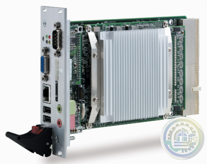
ADLINK CPCI-3840 3U CompactPCI Intel® Pentium® M Processor Module
-
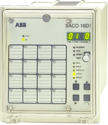
ABB Digital Annunciator Unit SACO 16D1
-
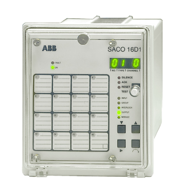
ABB SACO16D1-AA Digital Annunciator Unit
-
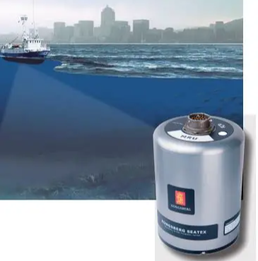
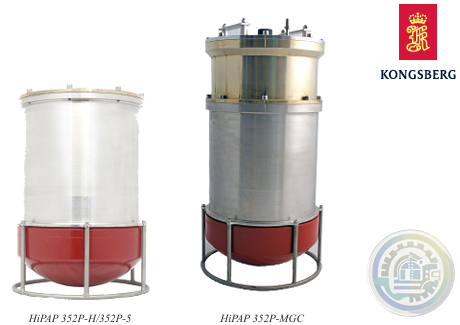
Kongsberg HIPAP® 352P PORTABLE HIGH PRESICION ACOUSTIC POSITIONING
-
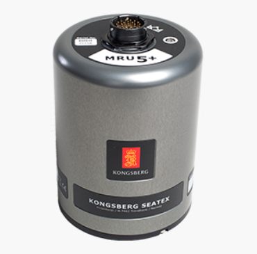
Kongsberg MRU 5 Motion Reference Unit
-
Kongsberg MRU 5+ Motion Reference Unit
-
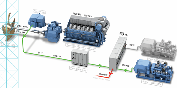
Kongsberg KONGSBERG MARITIME PROPULSION SYSTEMS Active Front End (AFE)
-
Kongsberg HiPAP 352P Portable acoustic positioning system
-
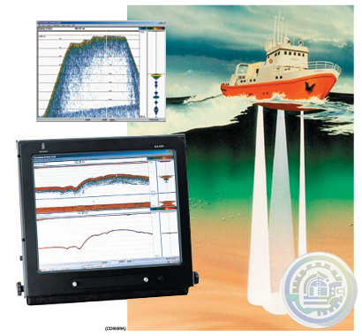
Kongsberg EA600 New generation precision hydrographic echo sounder
-
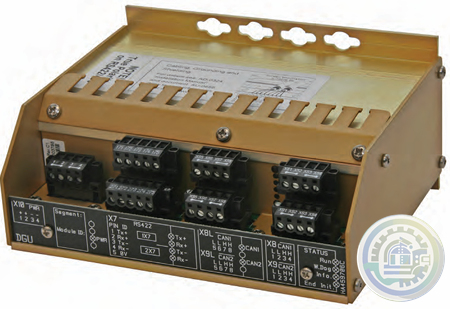
Kongsberg Digital Governor Unit (DGU) AutoChief® 600
-
Kongsberg AutoChief® 600 Propulsion Control System
-
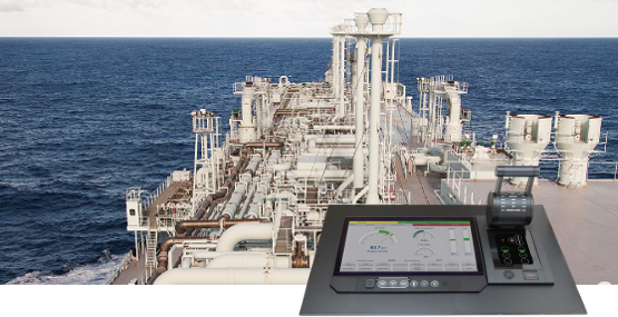
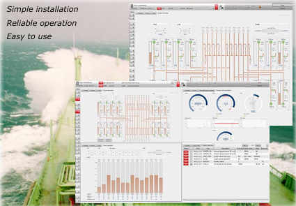
Kongsberg K-Chief Vessel Automation System
-
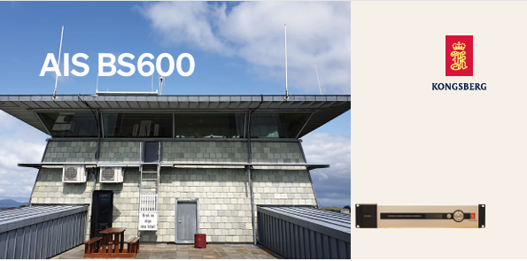
Kongsberg AIS BS600 Automatic Identification System - Base Station
-
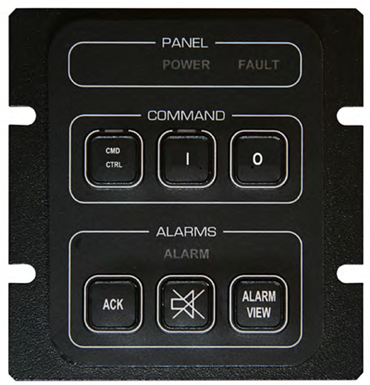
Kongsberg K-Chief 600 Alarm and Command Panel
-
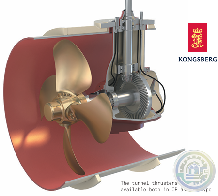
Kongsberg Tunnel Thrusters Type TT FP
-
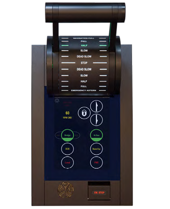
Kongsberg AutoChief®600 Lever Telegraph Unit (LTU11)
-
YOKOGAWA Model AW810D Wide Area Communication Router
-
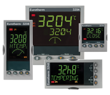
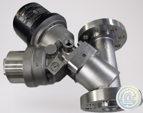
Watlow Eurotherm® 3200 Temperature/Process Controller
-
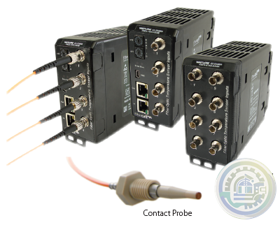
Watlow EtherCAT®, Fiber Optic Temperature Measurement and Control System
-
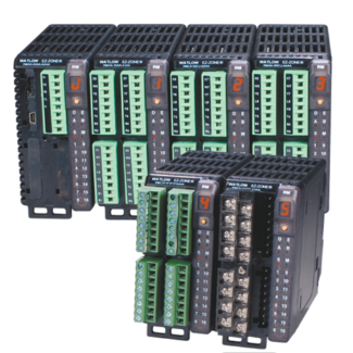
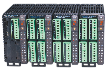
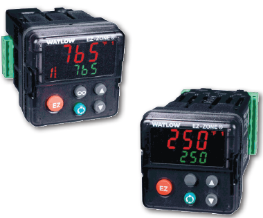
Watlow EZ-ZONE® RM Modular Controller Family
-
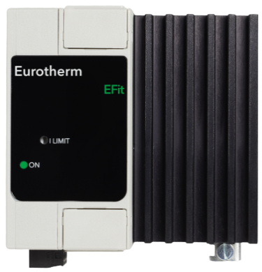
Watlow EFit SCR Power Controller
-
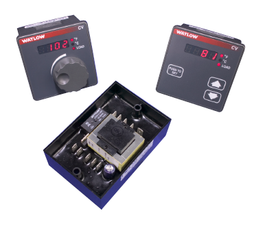
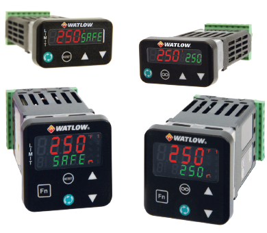
Watlow Basic Temperature and Limit Controllers
-
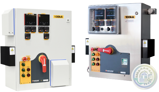
Watlow’s New WATCONNECT® Control Panels
-
Watlow EPack-2PH Compact SCR Power Controllers
-
Watlow Large and Extra-Large WATCONNECT® Panels
-
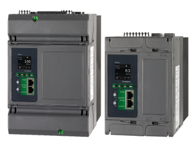
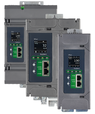
Watlow Eurotherm® EPack™ compact SCR power controllers-1PH -2PH -3PH
-
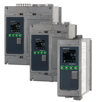
Watlow Eurotherm® EPack™ Lite Compact SCR Power Controllers
-
Watlow EPack™ Lite-1PH Compact SCR Power Controllers
-
Watlow’s new SERIES LS offers fixed limit set point temperature values
-
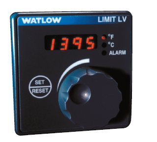
Watlow The SERIES LV limit family
-
Watlow’s family of microprocessor- based limit controllers SERIES LF
-
Watlow The EZ-ZONE RM controller simplifies thermal system management
-
Watlow The PM LEGACY™ series panel mount controller
-
Watlow EZ-ZONE® Remote User Interface (RUI)
-
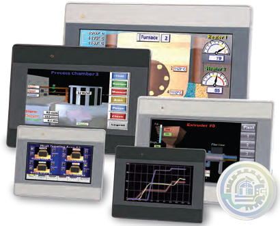
Watlow Silver Series EM Operator Interface Terminal
-
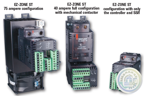
The EZ-ZONE® ST integrated solid state controller from Watlow®
-
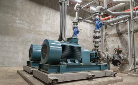
YOKOGAWA Cooling Water Pump Failure Prediction Monitoring
-
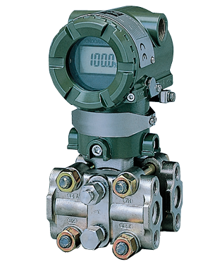
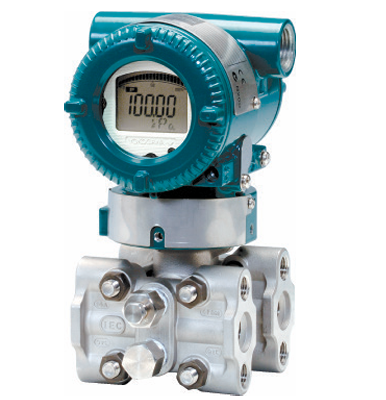
YOKOGAWA EJA Series Differential Pressure and Pressure Transmitters
-
YOKOGAWA EJA110E Diff erential Pressure Transmitter
-
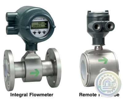
YOKOGAWA AXF Magnetic Flowmeter Series
-
YOKOGAWA Turbomachinery Controller Overview (FCN-500/FCN-RTU)
-
YOKOGAWA STARDOM FCN-RTU Autonomous Controller
-
YOKOGAWA FCN Autonomous Controller Hardware (FCN-100)
-
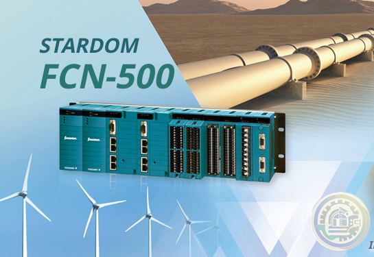
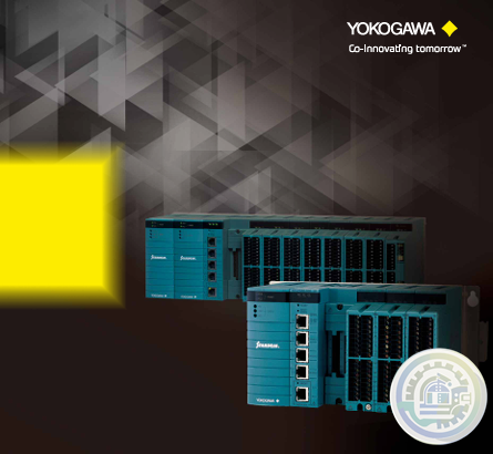
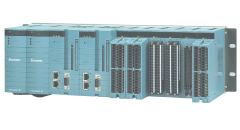
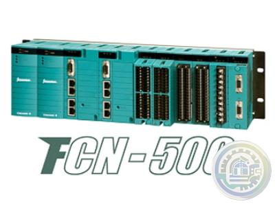
YOKOGAWA STARDOM FCN-500 Autonomous Controller
-
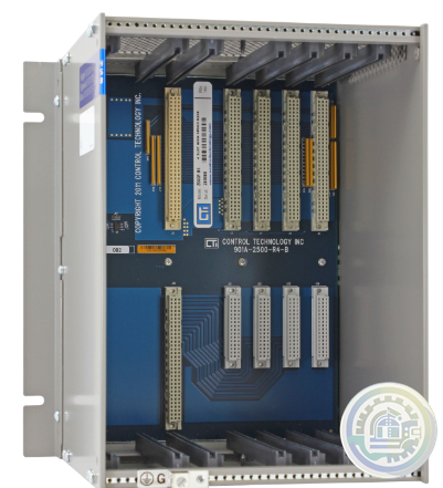
CTI 2500-R4 Four-Slot Base with High-Speed Channel
-
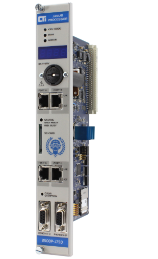
CTI 2500P-J750 Janus PAC with 3MB Project Memory
-
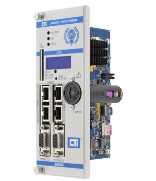
CTI 2500C-J750“Janus”Compact Programmable Automation Controller
-
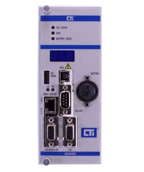
CTI 2500 Series® Compact Programmable Controllers
-
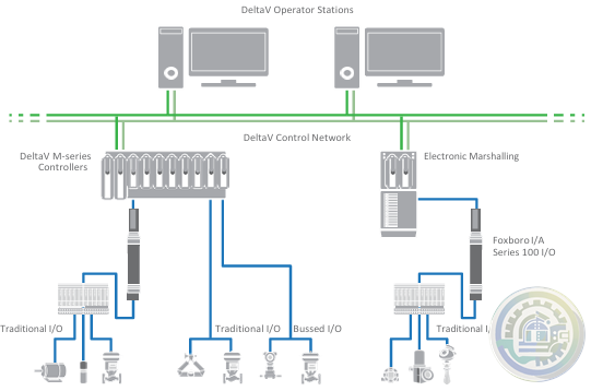
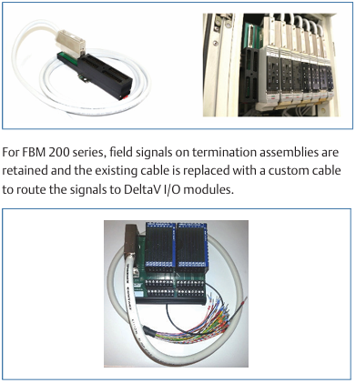
Emerson DeltaV™ Flex.Connect Solutions for Foxboro™ I/A Series 100 I/O
-
Emerson Modernization of Foxboro I/A Series® Systems to the DeltaV™ System
-
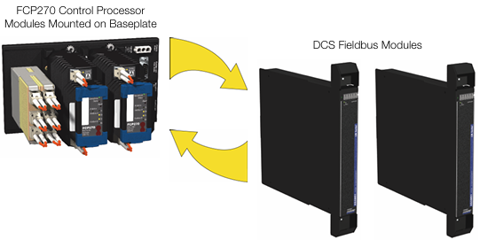
Foxboro DCS Fieldbus Modules for APACS+™ Automation Systems
-
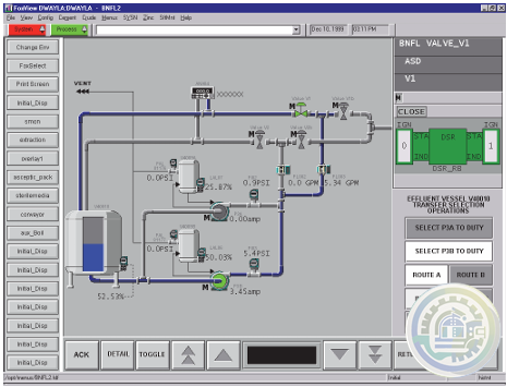
Foxboro Evo™ Process Automation System
-
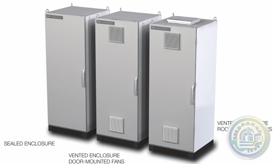
Foxboro™ DCS G61 Tricon Termination Enclosure
-
Foxboro G60 Tricon System Enclosure I/A Series® HARDWARE
-
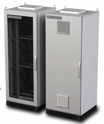
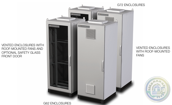
Foxboro G62 and G72 Tricon System and Termination Enclosures
-
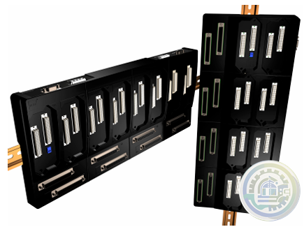
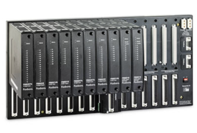
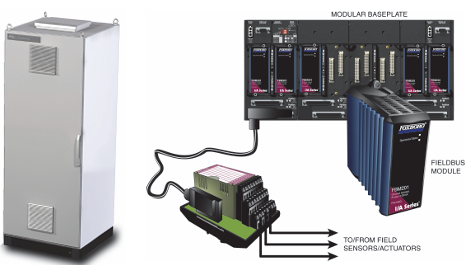
Foxboro I/A Series® Hardware DIN Rail Mounted Fieldbus Module Baseplate
-
Kongsberg K-Chief 600 Marine automation system
-
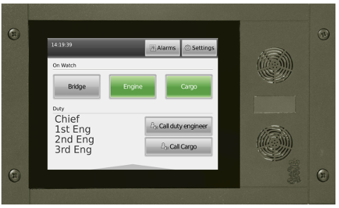
Kongsberg WCC 600 Watch Call Panels
-
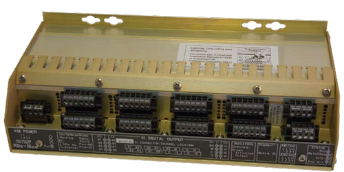
Kongsberg Distributed Processing Units Remote Digital Output (RDo-16xe)
-
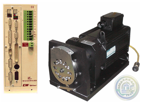
Woodward EM‐80 and EM‐300 Actuators All‐Electric Actuator System
-
Foxboro DCS FBM for Migration of Bailey® Systems
-
Foxboro Migration with FCP280 and DCS FBMs
-
Foxboro DCS Fieldbus Modules for Siemens APACS+™ Automation Systems
-
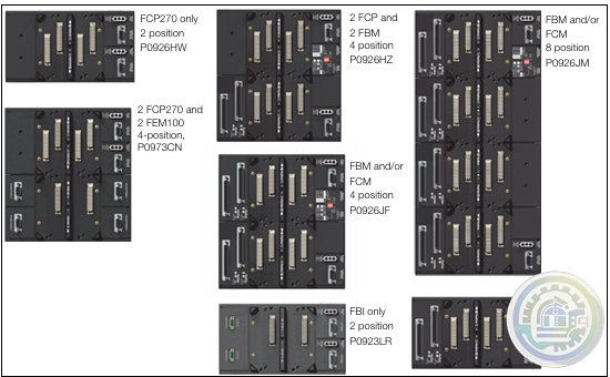
Foxboro 200 Series Baseplate Module Mounting
-
Foxboro Standard 200 Series Subsystem Overview
-
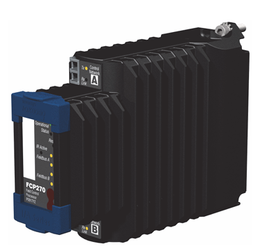
Foxboro Field Control Processor 270 (FCP270)
-
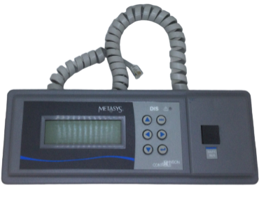
Johnson Controls DIS1710 Local Controller Display Installation Instructions
-
Johnson Controls FX-DIS Local Controller Display
-
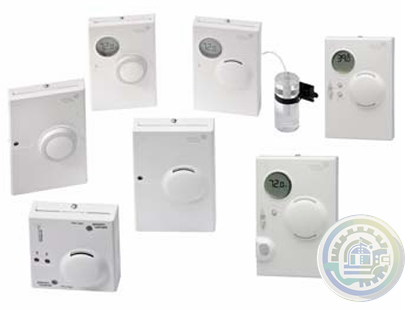
Johnson Controls WRZ Series Wireless Room Sensors
-
Woodward EM-80/EM-300 Actuator System
-
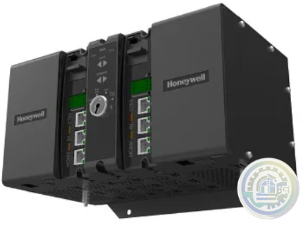
Honeywell ControlEdge™ PLC Modular Controllers
-
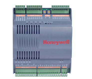
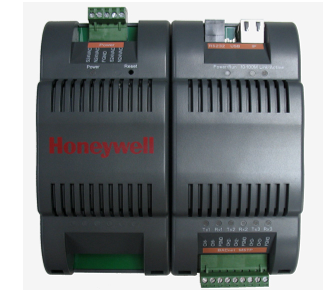
Honeywell CONTROLEDGE PCD Compact, Cyber Secure Control System
-
Honeywell M6410A, M7410F Non-Spring Return Cartridge Globe Valve Actuator
-
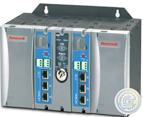
Honeywell ControlEdge™ HC900 How Does It Work?
-
Honeywell ControlEdge HC900 controller
-
Honeywell HC900 Functional Overview
-
Honeywell Optimizer Advanced Controllers are a family of next generation integration & plant controllers
-
Honeywell Optimizer Advanced Controller
-
Honeywell Excel Web II Control System
-
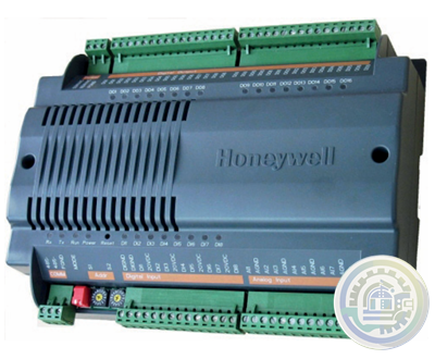
Honeywell CPO-PLANT Controller area of the site
-
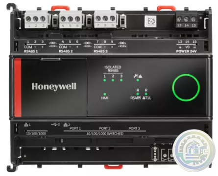
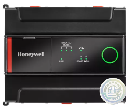
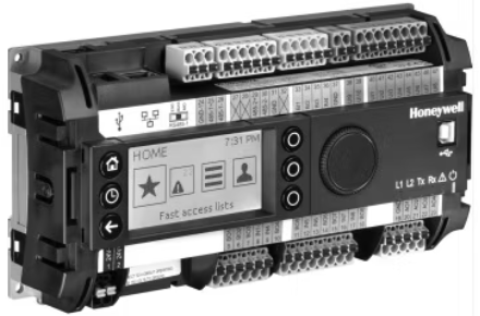
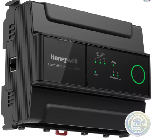
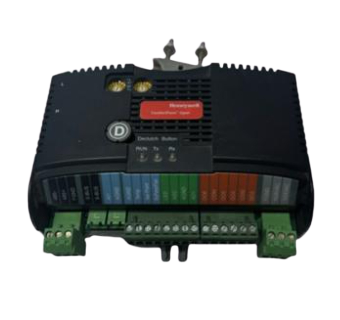
Honeywell ComfortPoint Niagara T1L VAV Controller
-
Honeywell ComfortPoint™ Open Plant Controller
-
Honeywell ComfortPoint Open CP-EXPIO (EXPANSION IO BOARD)
-
Honeywell ComfortPoint Open CPO-VAV2A-US (UNITARY CONTROLLER)
-
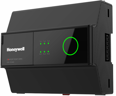
Honeywell ComfortPoint™ Open CPO-PC400 Plant Controller
-
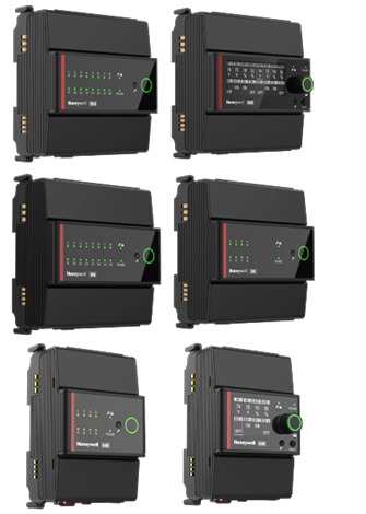
Honeywell I/O MODULES EXPANSION MODULES & WIRING ADAPTER
-
Honeywell CPO-DIO ComfortPoint Open (DIGITAL I/O CONTROLLER)
-
Honeywell CP-Core ComfortPoint Open
-
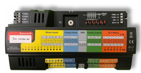
Honeywell CPO-IO830A ComfortPoint Open MIXED I/O MODULE
-
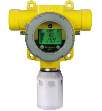
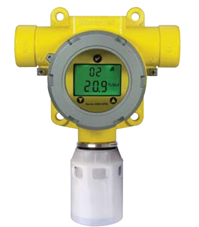
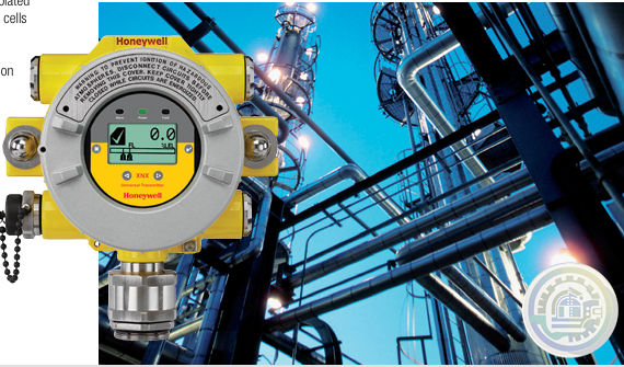
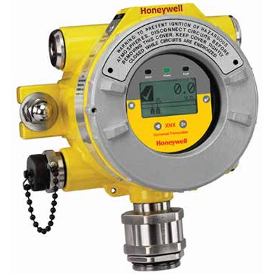
Honeywell Sensepoint XCD
-
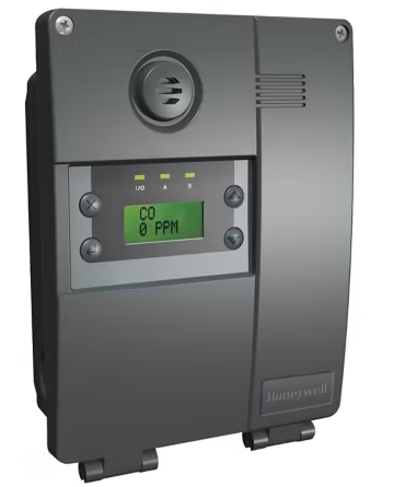
Honeywell E3Point Gas Detector
-
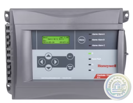
Honeywell 301C Controller
-
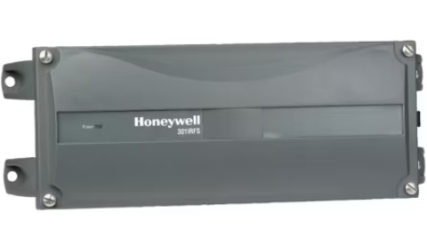
Honeywell 301IRF Refrigerant Gas Detector
-
Honeywell 301EM-20 Controller
-
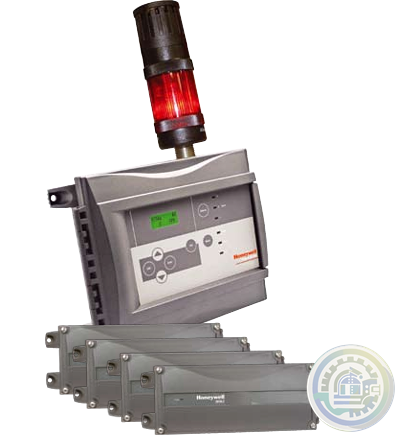
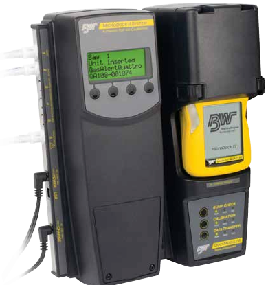
Honeywell Series 3000 MkII
- Baldor
- Glassman
- Johnson Controls
- Studer
- Watlow
- AEG
- ADVANCED
- KEBA
- Bristol Babcock
- Rolls-Royce
- Aerotech
- APPLIED MATERIALS
- Basler
- SAACKE
- BENDER
- Kollmorgen
- MEGGITT
- METSO
- MITSUBISHI
- MTL
- HIMA
- Siemens
- BACHMANN
- AMAT
- DEIF
- DELTATAU
- EATON
- ELAU
- LAM
- SCHNEIDER
- Advantest
- ABB
- GE
- Emerson
- Motorola
- A-B
- KUKA
- Abaco
- HITACHI
- SST
- Vibro-Meter
- Rexroth
- Prosoft
- DFI
- Scanlab
- Reliance
- Parker
- Woodward
- MOOG
- NI
- FOXBORO
- Triconex
- Bently
- ALSTOM
- YOKOGAWA
- B&R
- UNIOP
- KONGSBERG
- Honeywell
- Omron
- CTI
- EPRO
- Tell:+86-18144100983
- email:kongjiangauto@163.com
- Application:wind/ petroleum/ chemical/ natural gas/ Marine/ mining/ aviation/ electronics/ steel/ nuclear power/ electric power/ coking/ air separation and so on
- Series:PLC/ DCS/ servo/ analog/ Ethernet/ digital/ redundant module/ tension system/ excitation/ generator management/ human-machine interface/ detection card/ sensor/ AC drive/ etc
Wiring considerations
Follow the guidelines below when planning your system wiring.
• To limit the pickup of electrical noise, keep thermocouple and
millivolt signal wires away from power and load lines.
• For high immunity to electrical noise, use Alpha 5121 (shielded,
twisted pair) or equivalent wire for millivolt sensors; or use
shielded, twisted pair thermocouple extension lead wire
specified by the thermocouple manufacturer. Using the incorrect
type of thermocouple extension wire or not following the
correct polarity may cause invalid readings. See IEEE Std. 518,
Section 6.4.2.7 or contact your sensor manufacturer for additional details.
• When trimming cable leads, minimize the length of unshielded wires.
• Ground the shield drain wire at only one end of the cable. The preferred location is at the I/O chassis ground (See Figure 2.4).

• For maximum noise reduction, use 3/8 inch braid wire to
connect cable shields to the nearest I/O chassis mounting bolt.
Then connect the I/O chassis to earth ground (See Figure 2.4).
These connections are a requirement regardless of cable type.
• Tighten terminal screws. Excessive tightening can strip the screw.
• The open–circuit detector generates approximately 20 nano–
amperes into the thermocouple cable. A total lead resistance of
25 ohms (12.5 one–way) will produce 0.5 mV of error.
• Follow system grounding and wiring guidelines found in your
SLC 500 Modular Hardware Installation and Operation Manual,
publication 1747–6.2.
Output response
When the slot for this module is disabled, configuration words in the
SLC processor’s output image table are held in their last state and not
transferred to the module. When the slot is re–enabled, output image
table words are transferred to the module during the subsequent scan.
Installing and Wiring
This document gives you information about:
• avoiding electrostatic damage
• compliance with European Union directive
• determining the module’s chassis power requirement
• planning for sufficient enclosure depth
• choosing a module slot in a local I/O chassis
• installing the module
• wiring the module

Installing the Module
Follow this procedure:
ATTENTION
!
Never install, remove, or wire modules with power applied to the chassis or devices wired to the module.
1. Align the circuit board of the thermocouple module with the card guides located at the top and bottom of the chassis.
2. Slide the module into the chassis until both top and bottom retaining clips are secured.
Apply firm even pressure on the module to attach it to its backplane connector.
Never force the module into the slot.
3. Cover unused slots with the card slot filler, catalog number 1746–N2.
4. To remove, press the releases at the top and bottom of the module, and slide the module out of the chassis slot.

Module Addressing
When you enter the module ID in processor configuration (off-line),
the processor automatically reserves the required number of I/O
image table words. In the figure below, that section of the I/O image
table is designated by “slot e”. Its location in the I/O image table is
determined by the module’s slot location “e” in the I/O chassis. Slot
location “e” is a required addressing unit when referring to the
module in ladder logic. For the sample program’s data table layout

A-B 1756-OB32 module Rockwell ControlLogix 32 digital output
A-B 1756-OV32E module Rockwell ControlLogix 32 digital output
A-B 1756-OW16I module Rockwell ControlLogix 16 digital output
A-B 1756-OX8I module Rockwell ControlLogix 8 digital output
A-B 1756-PA72 Module Rockwell ControlLogix AC Power Supply
A-B 1756-PA75 Module Rockwell ControlLogix AC Power Supply
A-B 1756-PA75R Module Rockwell ControlLogix AC Power Supply
A-B 1756-PAR2 Module Rockwell ControlLogix AC Power Supply
A-B 1756-PAXT Module Rockwell ControlLogix XT Power Supply
A-B 1756-ON8 module Rockwell ControlLogix 8 digital output
A-B 1756-OV16E module Rockwell ControlLogix 16 digital output
A-B 1756-PB72 Module Rockwell ControlLogix DC Power Supply
A-B 1756-PB75 Module Rockwell ControlLogix DC Power Supply
A-B 1756-PB75R Module Rockwell ControlLogix DC Power Supply
A-B 1756-PBR2 Module Rockwell ControlLogix Power Supply
A-B 1756-PBXT Module Rockwell ControlLogix XT Power Supply
A-B 1756-PC75 Module Rockwell ControlLogix DC Power Supply
A-B 1756-PH75 Module Rockwell ControlLogix DC Power Supply
A-B 1756-PSCA2 Module Rockwell ControlLogix Adapter
A-B 1756-OB8 module Rockwell ControlLogix 8 digital output
A-B 1756-OB8EI module Rockwell ControlLogix 8 digital output
A-B 1756-OB8I module Rockwell ControlLogix 8 digital output
A-B 1756-OC8 module Rockwell ControlLogix 8 digital output
A-B 1756-OF4 module Rockwell ControlLogix 4 analog
A-B 1756-OF6CI module Rockwell ControlLogix 6 analog
A-B 1756-OF6VI module Rockwell ControlLogix 6 analog
A-B 1756-OF8 module Rockwell ControlLogix 8 analog
A-B 1756-OF8H module Rockwell ControlLogix 8 analog
A-B 1756-OG16 module Rockwell ControlLogix 16 digital output
A-B 1756-OH8I module Rockwell ControlLogix 8 digital output
| User name | Member Level | Quantity | Specification | Purchase Date |
|---|


Please do not listen to the advice of non-professional engineers! Cause equipment damage!


wechat/whatsapp:
Email: kongjiangauto@163.com
-
Vibro-meter vmf-RLC16-V111 200-570-101-015 200-570-000-111 Relay Card
-
Vibro-meter vmf-IOC4T 200560-101-017 200-560-000-111 I/O module
-
vmf cpum vmf-cmc16 200-530-111-013 200-530-100-014 Vibro-meter Monitoring system Modulee
-
Vibro-meter 200-595-045-114 | CPUM | Vibration Processor Module
-
Vibro-meter SIM-275A 200-582-500-013 state-of-the-art protection and monitoring module
Copyright © 2009 - 2024 Cld , All Rights Reserved K-JIANG All rights reserved


