-
Deif Du-2 / Mkiii Multil neas Ppm Protecci n Y Gesti n de Energ a 100-690vac
-
DEIF AGC 222 & IOM 220 advanced genset controller
-
Deif Delomatic 4 DGU 0005 Generator Control System PCM 4-1, IOM 4-1, SCM 4-2
-
DEIF PPM-3-DG PROTECTION AND POWER MANAGEMENT MEAS.VOLTAGE:100-690VAC, 0.5MA
-
DEIF AGC Plant Management (Genset Controller) 100132445.10
-
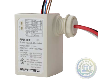
IR-TEC PPU-300 Power Pack & Controller
-
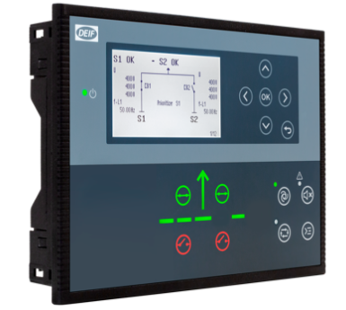
Streamline power transfer with DEIF's AGC 150 ATS controller
-
DEIF AGC 150 ATS: Advanced Generator Transfer Switch for Seamless Power Management
-
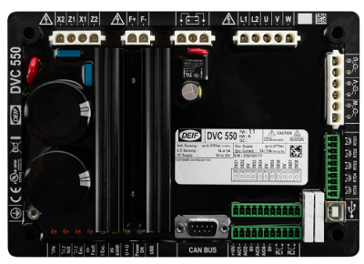
DEIF DVC 550 Automatic voltage control
-
DEIF Optimize Your Power Systems with DEIF's DVC 550
-
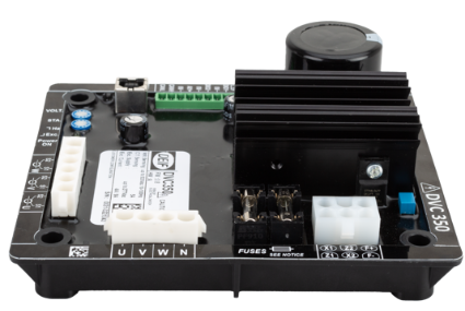
DEIF DVC 350 Digital automatic voltage regulator (AVR)
-
DEIF Advanced Features of DVC 350 Digital Automatic Voltage Regulator
-
DEIF Digital Voltage Controller DVC 550
-
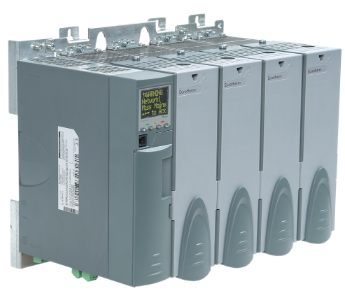
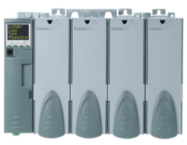
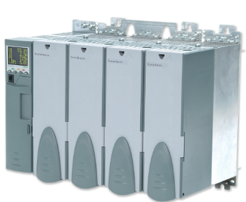
Watlow EPower™ Controller Revolutionary modularity and configurability to meet your needs
-
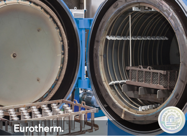
Watlow Eurotherm® EPower™ Controller
-
Watlow Eurotherm A standardized upgrade solution
-
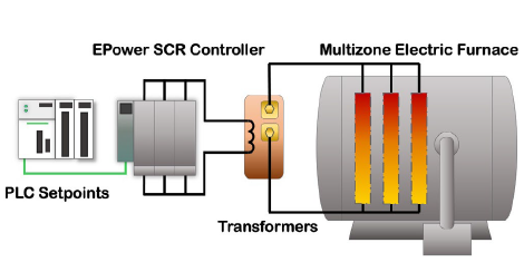
Watlow Eurotherm Cost efficiency for electric furnaces
-
Watlow Eurotherm Energy efficiency for electric heat treatment furnaces
-
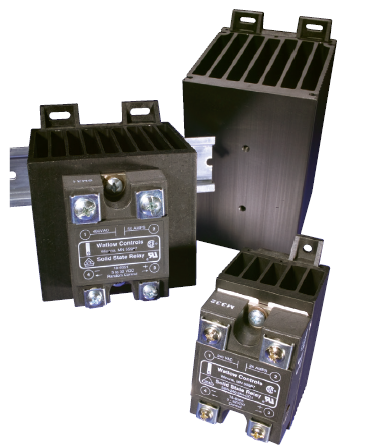
Watlow Solid State Relays (SSR)
-
Watlow DIN-A-MITE® D silicon controlled rectifier (SCR) power controller
-
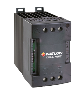
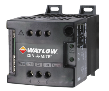
Watlow DIN-A-MITE® C silicon controlled rectifier (SCR) power controller
-
Watlow DIN-A-MITE® B Power Controller
-
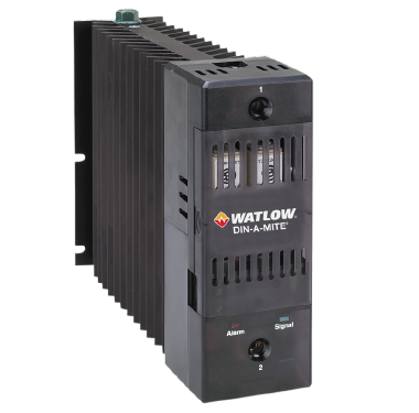
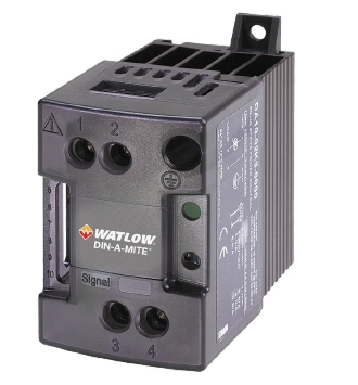
Watlow DIN-A-MITE® A Power Switching Devices
-
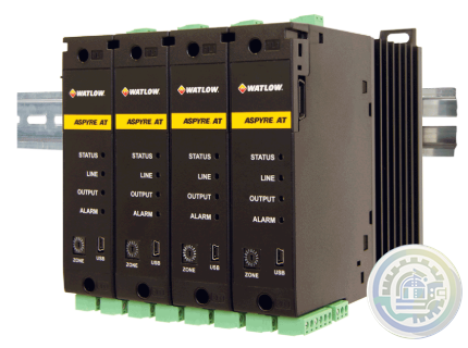
Watlow ASPYRE® AT Power Controllers
-
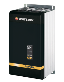
Watlow ASPYRE® DT SCR Power Controllers
-
Watlow PM PLUS™ Controller Features and Benefits
-
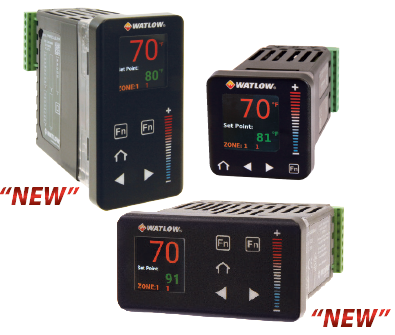
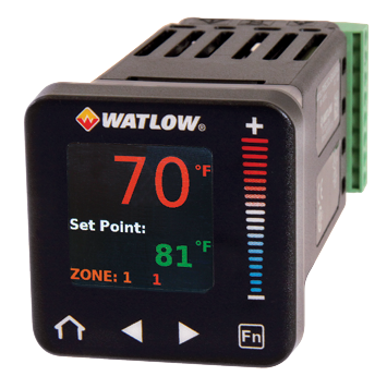
Watlow PM PLUS™ Controller
-
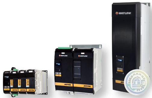
Watlow ASPYRE To Elevate Your System
-
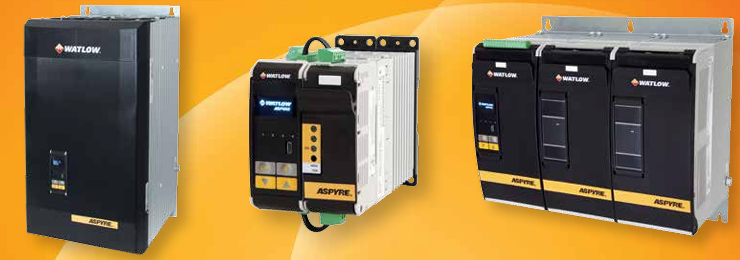
Watlow ASPYRE® DT Power Controllers
-
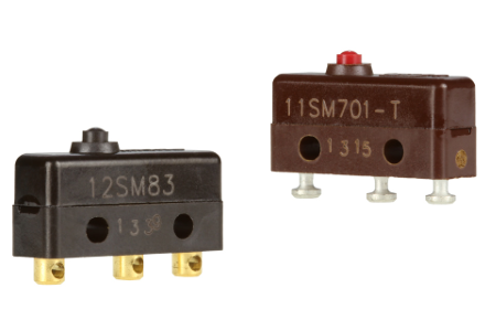
Honeywell MICRO SWITCH Premium Subminiature Basic Switches
-
HIMA SILworX API (application programming interface)
-
HIMA Automated testing with SILworX Smart Safety Test
-
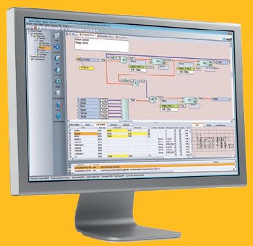
HIMA SILworX The world’s most advanced safety application manager
-
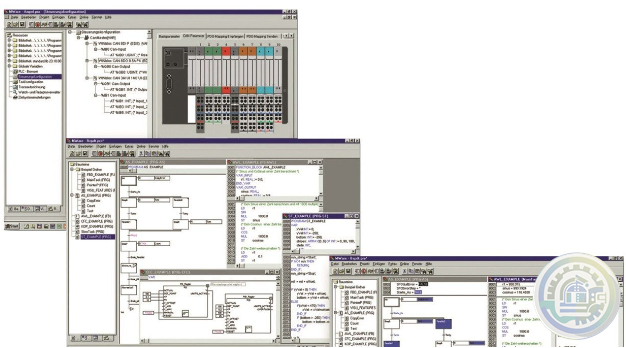
Eaton CODESYS software
-
Eaton CODESYS version 3 Integrated fieldbus configuration
-
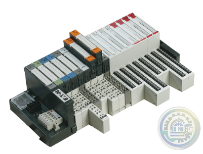
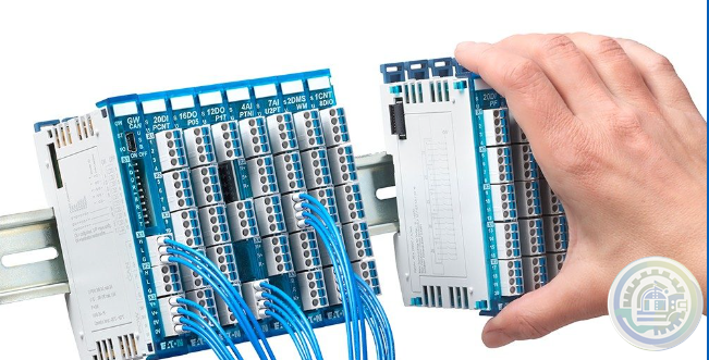
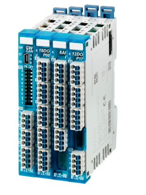
Eaton XI/ON I/O system
-
Eaton XN300 modules High modularity with a small footprint
-
Eaton XN300 I/O system
-
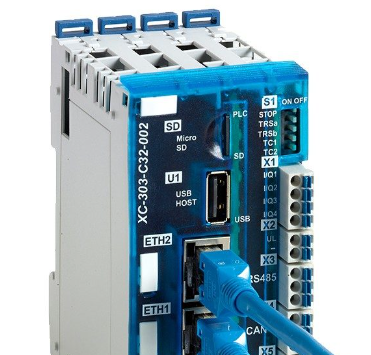
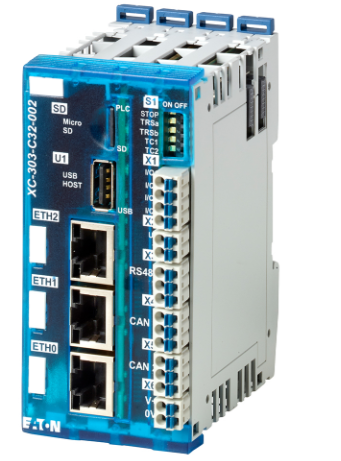
Eaton The XC300 modular PLC: Powerful communication
-
Eaton The three device variants of the XC300 Comprehensive functions and interfaces
-
Eaton XC300 modular programmable logic controllers
-
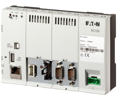
Eaton XC150 compact programmable logic controllers
-
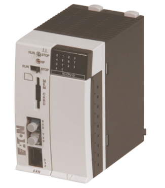
Eaton XC100/200 modular programmable logic controllers
-
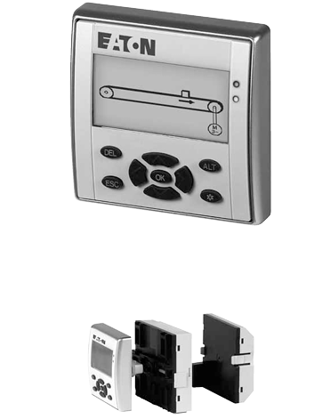
Eaton Multi-Function Display MFD-Titan
-
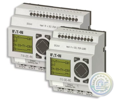
Eaton Legacy Easy programmable relays
-
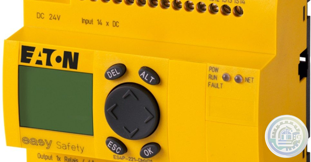
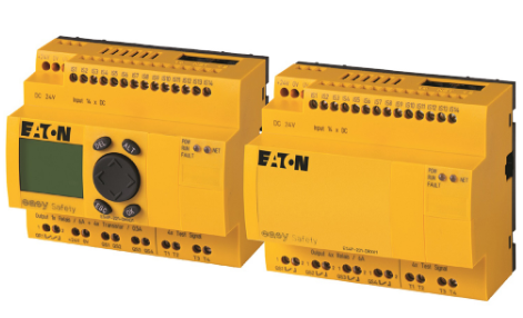
Eaton easySafety Safety for people and machines
-
Eaton easySafety programmable safety relays
-
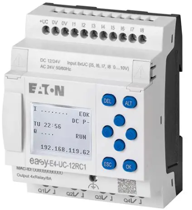
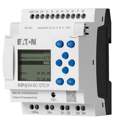
Eaton easyE4 programmable relays
-
Eaton easyE4 nano programmable logic controllers
-
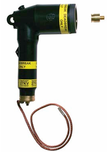
Eaton COOPER POWER SERIES DirectConnect elbow arrester
-
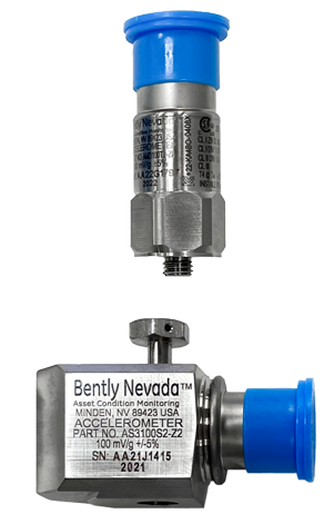
Bently Nevada IEPE Accelerometer Series
-
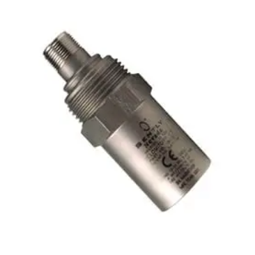
Bently Nevada Velocity Sensors & Accelerometers
-
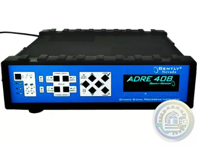
Bently Nevada ADRE - Data Acquisition & Machine Diagnostics System
-
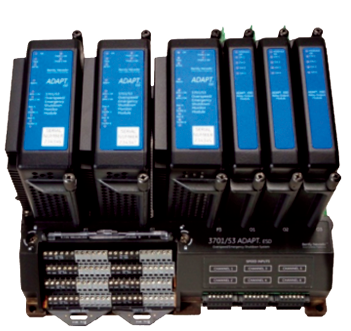
Bently Nevada 3701/55 Emergency Shutdown Device
-
Bently Nevada Asset Condition Monitoring
-
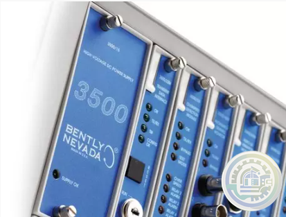
Bently Nevada 3500 Machinery Protection Systems
-
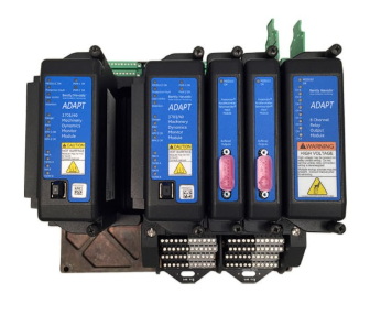
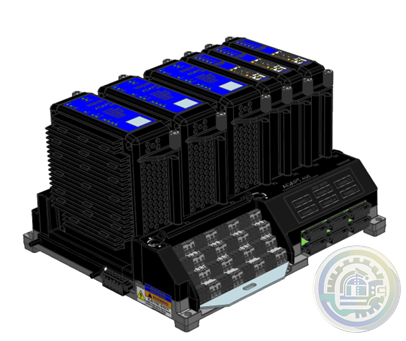
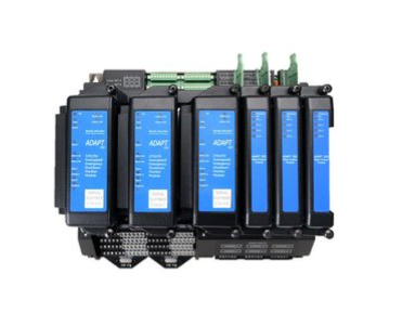
Bently Nevada ADAPT ESD Relay Module
-
Bently Nevada Typical (and recommended) applications of the ADAPT ESD
-
Bently Nevada 3701/55 ADAPT (ESD) Emergency Shutdown Device
-
Bently Nevada Online Condition Monitoring Systems
-
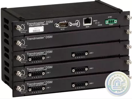
Bently Nevada Trendmaster Online Condition Monitoring System
-
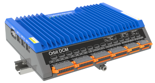
Bently Nevada Orbit Distributed Condition Monitoring
-
HIMA The HIJunctionBox is part of the Smart Safety Platform
-
HIMA HIJunctionBox Straightforward Safety
-
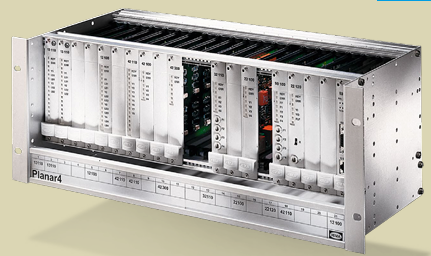
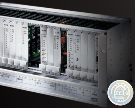
HIMA Planar4 Where Ultimate Safety Counts
-
HIMA HIQuad Lifecycle & Modernization
-
HIMA HIQuad X A New Dimension of Performance for Your Safety System
-
HIMA Communication Features of HIQuad X
-
HIMA Flexible SIL 4 Controllers SYSTEM FOR THE RAIL INDUSTRY
-
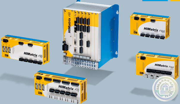
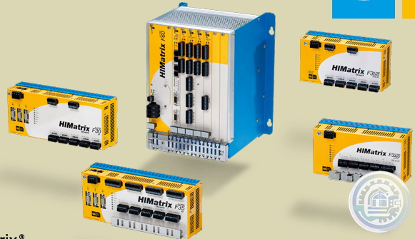
HIMA HIMatrix SYSTEMS Uniquely Fast, Uniquely Flexible
-
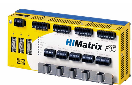
HIMA F35 HIMatrix Safety-Related Controller
-
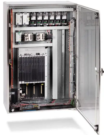
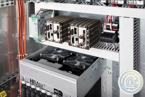
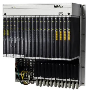
HIMA HIMax Flexible Safety for Maximum Profitability
-
HIMA X-COM 01 Communication Module
-
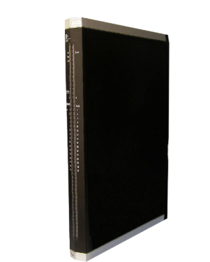
HIMA X-DI 64 01 Digital Input Module
-
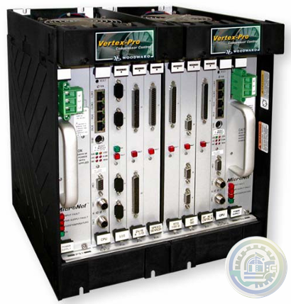
Woodward Oil Management
-
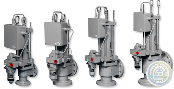
Woodward SonicFlo™ Gas Fuel Control Valve With Electric Trip
-
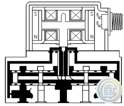
Woodward SonicFlo™ Gas Triple Coil Electrohydraulic Servo Valve Assembly
-
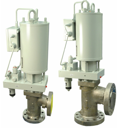
Woodward SonicFlo™ Gas Valves Hydraulically Actuated
-
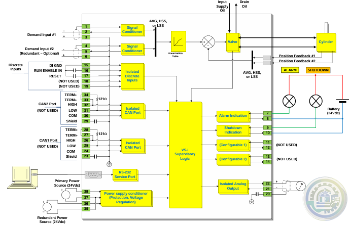
Woodward Discrete Output for Driver Status Indication
-
Woodward PWM Input for Position Demand
-
Woodward The Swift valve is a sonic flow-metering valve
-
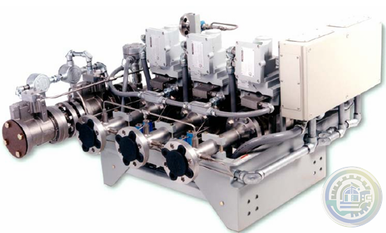
Woodward Swift™ Gas Metering System
-
Woodward LQ6 Liquid Fuel Valve with On‐board Driver
-
Woodward Fuel Metering System Integration Capabilities
-
Woodward DLE/DLN for Aeroderivative Turbine Platforms
-
Woodward Fuel Metering Systems
-
Woodward PG-07 controls Sequential spark ignition
-
Woodward PG-07 CONTROL SYSTEM FEATURES
-
Woodward PG-07 Power Generation & Stationary Control System
-
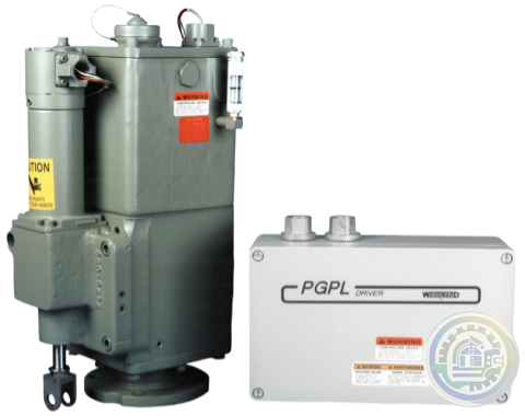
Woodward PG‐PL Governor
-
Woodward Air Management
-
Woodward Engine Actuation Systems
-
Woodward Fuel Injection and Ignition Systems
-
Woodward Fuel Control Systems
-
Woodward Smart Injector Technology Key Product Variants Include
-
Woodward P2X Features & Functionality
-
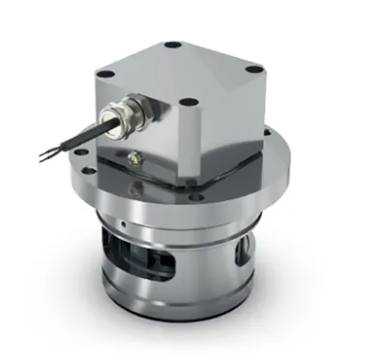
Woodward P2X Multi-Fuel Injectors
-
Woodward SOGAV Gas Valves
-
Woodward SOGAV Key Product Variants Include
-
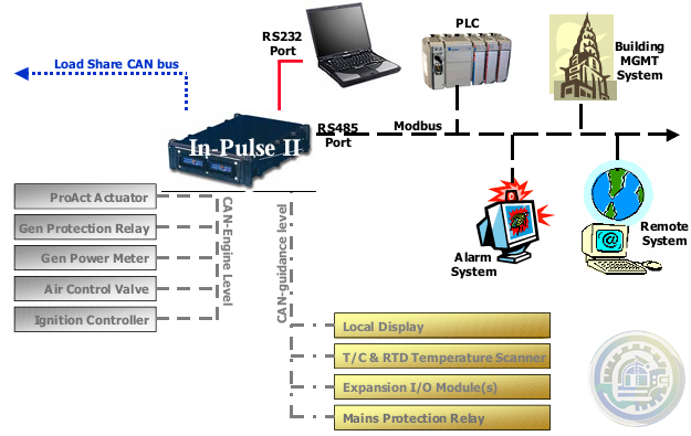
Woodward In-Pulse™ ll Self‐Diagnostics
-
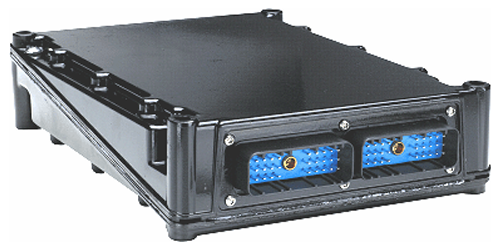
Woodward In-Pulse ll Fuel Injection Control
-
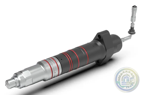
Woodward Dual-Fuel Injectors
-
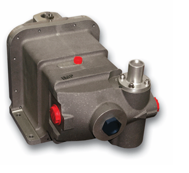
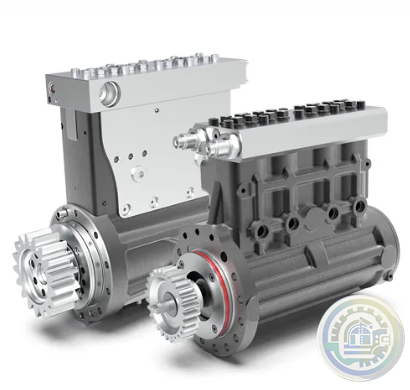
Woodward High-Pressure Pumps
-
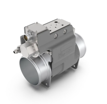
Woodward offers a growing line of air valves
-
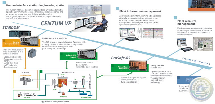
YOKOGAWA Turbine Control Solutions
- Glassman
- Johnson Controls
- Studer
- Watlow
- AEG
- ADVANCED
- KEBA
- Bristol Babcock
- Rolls-Royce
- Aerotech
- APPLIED MATERIALS
- Basler
- SAACKE
- BENDER
- Kollmorgen
- MEGGITT
- METSO
- MITSUBISHI
- MTL
- HIMA
- Siemens
- BACHMANN
- AMAT
- DEIF
- DELTATAU
- EATON
- ELAU
- LAM
- SCHNEIDER
- Advantest
- ABB
- GE
- Emerson
- Motorola
- A-B
- KUKA
- Abaco
- HITACHI
- SST
- Vibro-Meter
- Rexroth
- Prosoft
- DFI
- Scanlab
- Reliance
- Parker
- Woodward
- MOOG
- NI
- FOXBORO
- Triconex
- Bently
- ALSTOM
- YOKOGAWA
- B&R
- UNIOP
- KONGSBERG
- Honeywell
- Omron
- CTI
- EPRO
- Tell:+86-18144100983
- email:kongjiangauto@163.com
- Application:wind/ petroleum/ chemical/ natural gas/ Marine/ mining/ aviation/ electronics/ steel/ nuclear power/ electric power/ coking/ air separation and so on
- Series:PLC/ DCS/ servo/ analog/ Ethernet/ digital/ redundant module/ tension system/ excitation/ generator management/ human-machine interface/ detection card/ sensor/ AC drive/ etc
Analog Module Termination Cable Manufacturers ABB Model(s) ABB Bailey Infi 90
ABB Bailey Infi 90 and Net 90
Additional Information 33 foot length
Estimated Shipping Size Dimensions: 16.0" x 4.0" x 96.0" (40.6 cm x 10.2 cm x 243.8 cm)
Weight: 3 lbs 10.0 oz (1.4kg )
Tariff Code: 8544429000
Country of Origin: United States Ships from Webster NY, USA
Analog Module Termination Cable
• Termination for up to sixteen (16) TC / mV process signals within a Vertical column.
• All SD I/O modules & bases of all types (Singular or Redundant) AND (Compact or Full-size), are 100% fully compatible with each other.
Thus, Singular & Redundant, Compact or Full-size I/O modules can be mounted within a single, common HN800 I/O bus.
• Optional mechanical keying can be implemented to prevent insertion of the wrong I/O module type.
• Latching device on the base locks the base into position on DIN-Rail.
• Industry standard 35-mm DIN rail, Vertical Column mounting.

Features and benefits
Termination for up to sixteen (16) analog I/O process signals within a horizontal row.
All SD I/O modules & bases of all types (Singular or Redundant) AND (Compact or Full-size), are 100% fully compatible with each other.
Thus, Singular & Redundant, Compact or Full-size I/O modules can be mounted within a single, common HN800 I/O bus.
Optional mechanical keying can be implemented to prevent insertion of the wrong I/O module type.
Latching device on the base locks the base into position on DIN-Rail.
Industry standard 35-mm DIN rail, Horizontal row mounting.
Furthermore, the anti-pumping device only allows circuit-breaker closure if the following conditions
are present at the same time:
1. Closing spring fully charged
2. Opening mechanical pushbutton and/or opening release coils (-MO1/-MO2) are not active.
3. The circuit breaker is in the Open position.

Below is a side internal view of the EL mechanism and the associated anti-pumping component.
When the opening pushbutton or coils are activated the opening shaft lever pushes down on point C of the anti-pump device.
This causes the device to side down slot D in direction of arrow B.
Then the trigger portion A moves out from between the closing push-button and the closing shaft lever.
So if the closing button or signal is held active and the opening button or signal is then activated.
The trigger A will pull out from between closing shaft lever and the closing push button.
Once the open signal is released the trigger A will come to rest under the closing push-button and will
not return between the closing shaft lever and closing push-button until the button or closing command is released.
The closing push button is operated by the closing coil (MC) directly by the shaft closing device.
This allows the anti-pumping device to prohibit closing by manual or electrical means.
| User name | Member Level | Quantity | Specification | Purchase Date |
|---|


Please do not listen to the advice of non-professional engineers! Cause equipment damage!


wechat/whatsapp:
Email: kongjiangauto@163.com
-
GE LP-33 SERIES UPS DISPLAY & CONTROL PANEL LP33
-
GE CL06A300M IEC Contactor (50 Amp)
-
GE CR2962F2D Plugging Switch NIB
-
General Electric IC500A411DG2 Electrical Rectifier Semiconductor
-
GE IS200BICLH1AFE Interface Module 259B2431DB-G01 BICLH1A
Copyright © 2009 - 2024 Cld , All Rights Reserved K-JIANG All rights reserved


