A-B 1747-ASB Module Overview Remote I/O Adapter Module
1747-ASB Module Overview
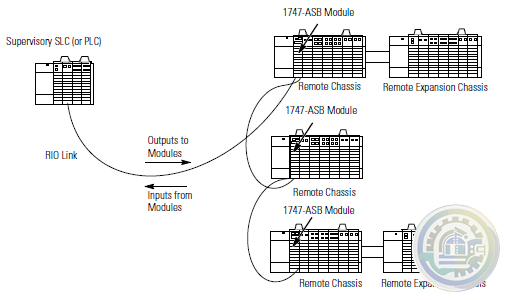
The 1747-ASB module is an SLC 500 single-slot, RIO communication link module. It
occupies the first slot (slot 0) of a 1746 remote chassis, where the SLC processor
normally resides.
The 1747-ASB module is an adapter, or slave, on the RIO link, and the master of the
remote chassis and remote expansion chassis in which it is installed. Remote
expansion chassis are optional. The module acts as a gateway between the scanner
and the I/O modules residing in the remote chassis and remote expansion chassis.
It maps the image of the I/O modules in its remote chassis and remote expansion
chassis directly to the SLC or PLC processor image.
Output data is sent from the scanner of either the SLC or PLC local chassis to the
1747-ASB module across the RIO link. This data is automatically transferred to the
output modules across the chassis backplane by the 1747-ASB module. Inputs from
the input modules are collected via the backplane by the 1747-ASB module and
sent back to the scanner across the RIO link. No user programming of the 1747-ASB
module is necessary.

Hardware Features

Required Tools and Equipment
Have the following tools and equipment ready:
• medium blade screwdriver
• (2) 1/2 watt terminating resistors (See page 18 for correct size.)
• an adequate length of RIO communication cable (Belden™ 9463) for your
specific application. (See page 18 for maximum cable distances.)
Determining System Power Requirements
Review the power requirements of your system to ensure that the chassis supports
placement of the 1747-ASB module. The adapter consumes 600 mA at 5V dc. For a
detailed list of device load currents, refer to the SLC 500 Fixed Hardware Style
Installation and Operation Manual, publication number 1747-6.21; the SLC 500
Modular Hardware Style User Manual, publication number 1747-UM011, or the
appropriate Technical Data sheet.
Slot Addressing
Slot Numbering
The 1747-ASB module is capable of controlling 30 slots. When expansion chassis
are used, the 1747-ASB module treats all of the I/O modules as if they are installed
in a single chassis.
The remote chassis and remote expansion chassis slots are numbered from 0 to 30.
The 1747-ASB module must reside in slot 0. Slots numbered 31 and above cannot
be used.
IMPORTANT Installing modules in slot 31 or above results in a module error.
Addressing I/O Modules
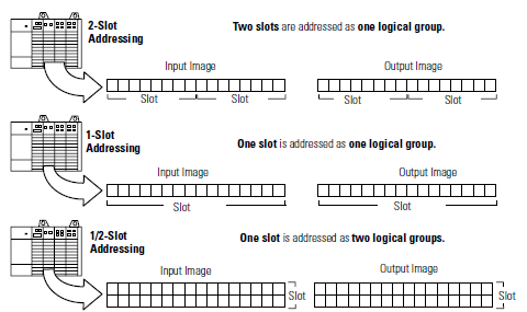
SLC and PLC processors address the I/O modules residing in the chassis by logical
rack and logical group. Slot addressing refers to how each chassis slot is assigned a
specific amount of the 1747-ASB module image. The amount depends on which
type of slot addressing you choose; 2-slot, 1-slot, and 1/2-slot addressing is
available, as shown below.
IMPORTANT Due to SLC and PLC addressing differences, when the 1747-ASB
module is used with an SLC processor, the image bit numbers are
0 to 7, 8 to 15 decimal. When the 1747-ASB module is used with
a PLC processor, the image bit numbers are 0 to 7, 10 to 17 octal.

- Informations
- Industry information
- ABB
- A-B
- GE
- MOOG
- NI
- YOKOGAWA
- FOXBORO
- BENTLY
- B&R
- UNIOP
- Abaco
- KONGSBERG
- Triconex
- HITACHI
- Emerson
- Honeywell
- Motorola
- Omron
- CTI
- Woodward
- Eaton
- EPRO
- KOLLMORGEN
- SST
- Scanlab
- Reliance
- DFI
- Prosoft
- Rexroth
- Vibro-Meter
- Mitsubishi Power
- Parker
- GEA
- MAN
- ALSTOM
- SBS
- PCH Engineering
- ZYGO
- HIMA
- BIFFI
- Advantest
- KUKA
- Full-V
- DEIF
- IBA
- Euresys
- Vishay
- Meggitt
- Aerotech
- Merlin Embedded
- Baker Hughes
- Horner
- Control Wave
- Schneider
- Siemens
- KEBA
- TEWS
- MERSEN
- Panasonic
- Ingersoll Rand
- Watlow
- Johnson Controls
- irtec
- Baldor
-
Kongsberg TRX32 FILTER (303067B) | Elektro Marine
-
Kongsberg MRU-M-MB3 | Motion Reference Unit
-
Kongsberg TRX32 303088 | eight-channel I/O module
-
Kongsberg MRU2 Motion Reference Unit
-
KONGSBERG MRU-M-SU1 Industrial Measurement Unit
-
Kongsberg RMP201-8 Versatile Remote Input/output System
-
Kongsberg dPSC 8100183 Dual Process Segment Controller
-
YOKOGAWA YS1700-100/A06/A31 Programmable indicating controller
-
YOKOGAWA YS1700-100/A06/A31 Programmable Indicating Controller
-
KS9-5*A | Yokogawa | MXL DSC Cabl
-
KS8-5*A | Yokogawa | MXL DSC Cabl
-
KS2-05*A | Yokogawa | MXL DSC Cabl
-
YOKOGAWA PW482-10 S2 Power Supply Module
-
Yokogawa SCP451-11 S1 Processor Module
-
YOKOGAWA SR1030B62 High-Frequency Module
-
Yokogawa CP451-50 S2 Processor Module
-
YOKOGAWA AAI143-H50 Analog I/O Modules
-
YOKOGAWA AMM42 2-Wire Transmitter Input Multiplexer Module
-
SDV144-S63 | Yokogawa | Digital Input Module
-
Yokogawa AIP830-111 Operation Keyboard for Single loop Operation
-
Yokogawa S9361DH00 Control Module / Terminal Board
-
Yokogawa ATK4A-00/S1 KS Cable Interface Adapter
-
YOKOGAWA PW701 Power Supply Module
-
YOKOGAWA Dual-Redundant V-Network Router AVR10D-A22010
-
YOKOGAWA PW441-10 Communication Module
-
YOKOGAWA VI451-10 S2 Communication Module
-
Yokogawa VC401-10 Coupler Modules
-
Yokogawa ALP121 PROFIBUS-DP Communication Module
-
Yokogawa NFAI841-S00/A4S00 Analog Input/Output Module
-
YOKOGAWA AIP591 Transceiver Control Module
-
YOKOGAWA AIP578 Transceiver Control Module
-
YOKOGAWA PW501 Power Supply Unit Brand
-
Yokogawa YNT511D-V42 Bus Repeater Module
-
YOKOGAWA AIP171 Transceiver Control Module
-
YOKOGAWA VI702 Vnet/IP Interface Card
-
2302-32-VLE-2 YOKOGAWA Data Acquisition Module
-
Yokogawa ATK4A-00 16-Channel KS Cable Interface Adapter
-
YOKOGAWA ALR121-S00 Serial Communication Module
-
CP461-50 | Yokogawa | Processor Module
-
Yokogawa AIP121-S00 Control Module
-
YOKOGAWA UR1800 Wireless Communication Module
-
Yokogawa| LC82 *A Redundant RL-Bus Interface Card
-
YOKOGAWA ST6 Industrial Control Module
-
YOKOGAWA ANR10D ER Bus Node Unit
-
YOKOGAWA SDV144-S13 S1 Digital Input Module
-
YOKOGAWA NFAI143-H00 analog I/O module
-
YOKOGAWA EB501 Bus Interface Module
-
Yokogawa CP451-10-S2 High-Performance Processor Module
-
YOKOGAWA V0/E1/TCAM/L08 High-Precision Temperature Controller
-
YOKOGAWA VO/E2/TCDM24/L8 High-Precision Temperature Controller
-
YOKOGAWA 16137-119 Process Control Module
-
YOKOGAWA 16114-500 I/O Module for Process Control Systems
-
Yokogawa PSCDM024DCBAN - Critical Discrete Module
-
YOKOGAWA 16137-151 Digital Input Module
-
YOKOGAWA 16137-188 Digital Input Module
-
YOKOGAWA 16137-222 Digital Input Module
-
YOKOGAWA 16137-223 Digital Input Module
-
YOKOGAWA 16137-153 Digital Input Module
-
Watlow SUB21/IV10 0-10 V input adaptor
-
Watlow ITOOLS/NONE/USB U SB configuration kit
-
Watlow CTR500000/000 100 A Current transformer
-
Watlow CTR400000/000 50 A Current transformer
-
Watlow CTR200000/000 25 A Current transformer
-
Watlow CTR100000/000 10 A Current transformer
-
Watlow SUB35/ACCESS/249R.1 2.49R Precision resistor
-
Vibro-meter vmf-RLC16-V111 200-570-101-015 200-570-000-111 Relay Card
-
Vibro-meter vmf-IOC4T 200560-101-017 200-560-000-111 I/O module
-
vmf cpum vmf-cmc16 200-530-111-013 200-530-100-014 Vibro-meter Monitoring system Modulee
-
Vibro-meter 200-595-045-114 | CPUM | Vibration Processor Module
-
Vibro-meter SIM-275A 200-582-500-013 state-of-the-art protection and monitoring module
-
Vibro-meter VM600 RLC16 200-570-000-111 200-570-101-015 Relay Card
-
Vibro-meter VM600 RPS6U 200-582-600-013 cutting-edge monitoring module
-
Vibro-meter VM600 CMC16 200-530-025-014 200-530-111-013 input/output card
-
Vibro-meter 200-570-000-014 200-570-101-013 VM600 Protection Module
-
Vibro-meter 620-002-000-113 620-003-111-112 VM600 XIO16T input/output card
-
Vibro-meter 600-003 620-001-001-116 VM600 XMV16 input/output card
-
Vibro-Meter 444-680-000-511 Level Detector & Proximity Sensor
-
Vibro-meter VM600 MPC4 200-510-111-034 200-510-070-113 Module
-
Vibro-Meter IOCN 200-566-000-113 | I/O Communication Node
-
Vibro-meter VM600 IOC16T 200-565-000-013 / 200-565-101-013 Industrial Control Module
-
Vibro-Meter 200-566-000-012 VM600 IOCN Communication board
-
Vibro-meter 200-560-000-113 VM600 power supplies Module
-
VIBRO 573-935-202C - High-Accuracy Interface Module
-
Vibro-meter 200-595-002-011 Modular Safety Relays
-
200-560-000-016 VIBRO I/O Module
-
YOKOGAWA 8662570000 Terminal Module
-
YOKOGAWA 8596020000 Terminal Module
-
YOKOGAWA 8662560000 Terminal Module
-
YOKOGAWA PSCAMAAN | Process Control Analog Input Module
-
YOKOGAWA DR1030B60 High-Precision Pressure Transmitter
-
Yokogawa adv551 Digital I/O Modules
-
Yokogawa aai543 Analog I/O Modules (for FIO)
-
YOKOGAWA LR 4220E Level Controller Module
-
Yokogawa SR1008B62 Signal Relay Module
-
SC200S | Yokogawa Electric Corporation
-
Yokogawa PW301 Power Supply
-
YOKOGAWA NP53*C - Precision Control Module
-
Yokogawa F3YD64-1A Basic Input/Output Modules
-
Yokogawa F3XD64-3N Basic Input/Output Modules
-
Yokogawa F3WD64-3N Input/Output Module
-
Yokogawa F3SP21-0N CPU Module
-
YOKOGAWA F3PU10-0N Power Supply Module
-
YOKOGAWA F3PU06-0N Power Supply Module
-
YOKOGAWA F3NC02-0N Positioning Module
-
YOKOGAWA F3NC01-0N Positioning Module
-
YOKOGAWA PLC F3LC21-1N MULTI-LINK MODULE
-
YOKOGAWA F3BU06-0N Base Module
-
Honeywell DC-TFB412 51307618-176 Control Module
-
Honeywell DC-TCF901 51307593-176 9-Port Control Firewall Module
-
Honeywell DC-TCF901 cutting-edge control module
-
Honeywell DC-TFB412 Circuit Board
-
LVCDJW00000750A Watlow (Temperature Limit Controller)
-
Watlow 84700-0003 Dust cover
-
Watlow 847290006 USB type A panel mount with 2 m cord
-
Watlow RJF 21N SCC RJ45 receptacle with self closing cap
-
Watlow USBBF 21N SCC USB - B receptacle with self closing cap
-
Watlow USBF 21N SCC USB - A receptacle with self closing cap
-
Watlow 0600-0097-0000 Mixed I/O Flex Modules Quick Start Guide
-
Watlow 0600-0096-0000 High Density Flex Modules Quick Start Guide
-
Watlow 0600-0095-0000 Communications Flex Modules Quick Start Guide
-
Watlow 0600-0094-0000 F4T Controller Quick Start Guide
-
Watlow 0600-0093-0000 Setup and Operations User Guide
-
Watlow 0600-0092-0000 Installation and Troubleshooting User Guide
-
Watlow 0822-0769-0000 Module slot plug (for vacant F4T slots without flex modules
-
Watlow 0830-0858-0000 Replacement battery
-
Watlow 0830-0808-0002 (CAPUSB-A) Rubber plug USB host
-
Watlow 0830-0808-0001 (CAPUSB-MB5) Rubber plug USB mini
-
Watlow 0601-0001-0000 Controller support tools (DVD)


wechat/whatsapp:
Email: kongjiangauto@163.com
-
Vibro-meter vmf-RLC16-V111 200-570-101-015 200-570-000-111 Relay Card
-
Vibro-meter vmf-IOC4T 200560-101-017 200-560-000-111 I/O module
-
vmf cpum vmf-cmc16 200-530-111-013 200-530-100-014 Vibro-meter Monitoring system Modulee
-
Vibro-meter 200-595-045-114 | CPUM | Vibration Processor Module
-
Vibro-meter SIM-275A 200-582-500-013 state-of-the-art protection and monitoring module
Copyright © 2009 - 2024 Cld , All Rights Reserved K-JIANG All rights reserved
