
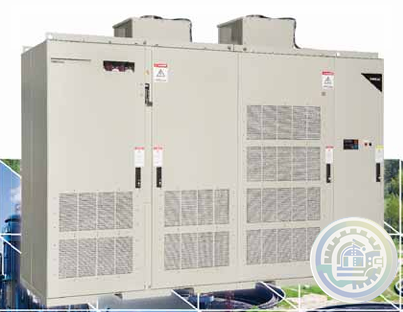
TMEIC TMdrive-MVe2 Reactive Power Control
Exceptional by Design™
Built-in Reliability and Performance
What makes the TMdrive-MVe2 Exceptional by Design™?
• Very High Reliability - 15 year MTBF
• Simple design
• Clean power to the utility system & motor
• Built-in Reactive Power Control
• Minimal spare parts
• Long-life film capacitors
• 24 hour x 365 day live support in North America
• Remote Connectivity troubleshooting built-in
Let's focus on the TMdrive-MVe2's Exceptional by Design™ feature: Built-in Reactive Power Control
All Variable Frequency Drives (VFDs) provide motor speed control (with potential energy savings and improved process control),
and some degree of motor protection. Voltage-source VFDs (typically with diode rectifiers and capacitor DC link) isolate the
poor power factor of their connected motors from the utility. For example, a motor with a power factor of .82 lagging would
have its power needs met by the output of the VFD, while the input reflects a much improved power factor of (typical) 0.95
lagging.
TMEIC’s TMdrive-MVe2 VFD input converter is configured with a unique “Active Front End” that uses active switches in place of
diode rectifiers. This allows the converter of the VFD to hold unity power factor at its input terminals. But the TMdrive-MVe2
and control goes beyond that and can actually correct the system Power Factor demands of other nearby utility loads without
adding capacitors.
Utility Plant Power
Typical Industrial loads such as shown in the one-line below consist of motors for plant processes, special equipment unique
to the facility, and other loads such as plant lighting and HVAC. In AC systems, the current that flows is divided into two
components, real power measured in kiloWatts (kW) and reactive power measured in kilovars (kVARs). Both types of power
draw current (amperes) from power delivery equipment such as transformers, cable, and switchgear. Current flow results in
voltage drop, heating and wasted energy.
kilowatts and kVARs
What is a kilowatt? kW is the accepted measure of the real energy consumed by any process. It is the product of volts and the
part of the total amps flowing that does real work, divided by 1000. This current is called “real” current, and flows in phase
with the voltage. This includes the “work” that produces heat in the cables and power delivery gear.
Describing “What is a kVAR?” is a little more difficult. A kVAR is the accepted measure of reactive power, equal to the product
of the volts and the part of the current that is “reactive” divided by 1000. Reactive current is the current that flows out of
phase with the supply voltage. Reactive current supplying motors lags in time behind the voltage and the real current, as in A
below. Reactive current that supplies capacitors leads in time ahead of the voltage and the real current, as in B below. Lagging
reactive current magnetizes motors and transformers.
The real power (kW) and the reactive power (kVAR) are related like the legs of a right triangle as in the figure at the above
right. Each of the sides is shown as an arrow, called vectors. Since they are at right angles, they cannot simply be added together.
The longer vector (kVA) represents the total current (amperes) and the load on the system. The ratio [kW / kVA] of real power
(kW) to apparent Power (kVA) is called the power factor (pf). The angle shown as A is the power factor angle. If all kVAR were
eliminated, the apparent power (kVA) and real power (kW) would be equal and the power factor would be unit or 1.00.
- Informations
- Industry information
- Others
- Autronica
- ABB
- A-B
- GE
- MOOG
- NI
- YOKOGAWA
- FOXBORO
- BENTLY
- B&R
- UNIOP
- KONGSBERG
- Triconex
- HITACHI
- Emerson
- Honeywell
- Motorola
- Omron
- CTI
- Woodward
- Eaton
- EPRO
- KOLLMORGEN
- SST
- Scanlab
- Reliance
- Prosoft
- Rexroth
- Vibro-Meter
- Mitsubishi Power
- Parker
- ALSTOM
- PCH Engineering
- SBS
- HIMA
- BIFFI
- Advantest
- KUKA
- DEIF
- IBA
- Euresys
- Meggitt
- Aerotech
- Merlin Embedded
- Baker Hughes
- Horner
- Control Wave
- Siemens
- Schneider
- KEBA
- TEWS
- Ingersoll Rand
- MERSEN
- Panasonic
- Watlow
- Johnson Controls
- Alfa Laval
- Bachmann
- Hirschmann
- ZYGO
- GUTOR
- ICS TRIPLEX
- OEMAX
- Beckhoff
- Nidec
-
TMEIC KPAD-3122A A3XAP02 LCD Display With Key Pad
-
Nidec Drives S100-02463 General Purpose Micro AC Drive
-
Nidec Drives S100-02463 General Purpose Micro AC Drive
-
Nidec Drives S100-01D13 General Purpose Micro AC Drive
-
Nidec Drives S100-01D73 General Purpose Micro AC Drive
-
ABB 3BUS208720-001 POWER SIGNAL INTERCONNECT
-
METSO A413345 Industrial Control Module
-
METSO A413177 Industrial Control Module
-
METSO A413222 Address Module Count Verification
-
METSO D100532 Control Module
-
METSO ADC5483-D200136L Power Supply Module
-
METSO A413313 Industrial Control Module
-
METSO A413310 Industrial Control Module
-
METSO A413659 Industrial Control Module
-
METSO D100314 Industrial Reliability Enhancement Component
-
METSO A413665 Industrial Control Module
-
METSO A413325 IPU Power Unit Module
-
METSO A413654 Real-time Control Module
-
METSO A413110 Industrial Process Control System
-
METSO A413160 Industrial Process Control System
-
METSO A413144 Industrial Control Module
-
METSO A413152 Industrial Control Module
-
METSO A413146 Timer & Memory Management Module
-
METSO PIC2 A413240A PCB Board
-
METSO A413150 Industrial Control Module
-
METSO A413140 analog input module
-
METSO A413111 analog input module
-
METSO AIU-8 A413125 analog input module
-
METSO 02VA0093 Control Module for Industrial Automation
-
METSO 020A0082 Process Control Optimization Module
-
METSO 02VA0153 Control Module for Industrial Automation
-
METSO 02VA0193 IOP Module
-
METSO 02VA0175 I/O Module
-
METSO D100308 Expansion Module
-
Metso D200175 Personality Module
-
Metso Automation D201471 Version 01 Or 05 DOI4 Module
-
Metso Automation D201138 IBC Controller Module
-
Metso Automation DOI4R0 PLC Card. 3D-27
-
Metso Automation D201776 ACN PO DC PLC Control Server Computer
-
ABB AC 800PEC CIO-FU PC D235 A101 3BHE032025R0101 Combined Input Output
-
ABB PFSA240 Roll DC Supply Unit 3BSE073476R1
-
ABB PFSA107-Z42 DTU Stressometer Digital Transmission Unit
-
GE AT868-2-1-1 Panametrics Ultrasonic Liquid Flow Transmitter
-
Beckhoff EKM1101 | EtherCAT Coupler with ID switch and diagnostics
-
Beckhoff EK1101-0080 | EtherCAT Coupler with ID switch, Fast Hot Connect
-
Beckhoff EK1101-0010 | EtherCAT Coupler with ID switch, Extended Distance
-
Beckhoff EK1101-0008 | EtherCAT Coupler with ID switch and M8 connection
-
Beckhoff EK1101 | EtherCAT Coupler with ID switch
-
Beckhoff EK1000 | EtherCAT TSN Coupler
-
Beckhoff EK1100-0008 | EtherCAT Coupler with M8 connection
-
Beckhoff EC1100 | EtherCAT Coupler, RJ45, angled, push-in
-
Beckhoff EK1100 | EtherCAT Coupler
-
KEBA KeDrive D3-DP Supply unit
-
KEBA KeDrive D3-DU Motion control accessories
-
KEBA KeDrive D3-DU 3x5 Safety controller
-
KEBA KeDrive D3-DA axis controller BG3+4
-
KEBA KeDrive D3-DA axis controller BG1+2
-
KEBA KeDrive D3-DP 310 supply module
-
KEBA KeDrive D3-DL 300 charging module
-
KEBA ServoOne Drive system for safe automation solutions
-
KEBA KeDrive D5 The single-axis controller without compromise
-
KEBA KeControl C5 - UE 550 USB expansion card
-
KEBA KeControl C5 - FE 560 Multi-protocol fieldbus expansion card
-
KEBA KeControl C5 - FE 573 EtherCAT master expansion card
-
KEBA KeControl C5 - FE 571 EtherCAT master expansion card
-
KeDrive D3 controls D3-DU 365/B Control modules
-
KeDrive D3 controls D3-DU 365/A Control modules
-
KeDrive D3 controls D3-DU 335/B Control modules
-
KeDrive D3 controls D3-DU 335/A Control modules
-
KeDrive D3 controls D3-DU 360/B Control modules
-
KeDrive D3 controls D3-DU 360/A Control modules
-
KeDrive D3 controls D3-DU 330/B Control modules
-
KeDrive D3 controls D3-DU 330/A Control modules
-
KEBA KeControl C1 Control modules CP 057/Y
-
KEBA KeControl C1 Control modules CP 056/Y
-
KEBA KeControl C1 Control modules CP 056/E
-
KEBA KeControl C1 Control modules CP 035/M
-
KEBA KeControl C5 CP 507/C Control units
-
KEBA KeControl C5 CP 507/A Control units
-
KEBA KeControl C5 CP 505/A Control units
-
KEBA KeControl CP 503/A Control units
-
KEBA KeControl C5 CP 530/C Control modules
-
KEBA KeControl C5 CP 520/C Control modules
-
KEBA KeControl C5 - CP 5x0 Control modules
-
KEBA KeControl C5 - CP 50x Controls / Control units
-
KEBA KeSafe C5 SDM 570 Extension Module
-
KEBA KeSafe C5 SCP 501 Safety Controller
-
KEBA KeDrive D3-ES energy storage device
-
KEBA KeDrive D3-EM energy manager
-
KEBA KeDrive D3-DP 301-x-A2xx passive supply units
-
KEBA KeDrive D3-DP 301/x-45xx passive supply units
-
KEBA KeDrive D3-DP 300/x-22xx passive supply units
-
KEBA KeDrive D3-DP 300/x-10xx passive supply units
-
KEBA KeDrive D3-AC all-in-one multi-axis controller
-
Autronica 116-AP-MAR-PLATE-BUR AP ON MOUNTING PLATE W BUR
-
Autronica 116-AP-MAR-PLATE AP ON MOUNTING PLATE WO BUR
-
Autronica 116-AP-MAR-CAB AP IN CABINET WO BUR
-
Autronica 116-AP-MAR-CAB-BUR AP IN CABINET W BUR
-
Mitsubishi Q00JCPU-S8 Universal Programmable Logic Controller (PLC) CPU
-
FX3U-128MT/ESS FX3U128MTESS FX3U-128MT-ESS MITSUBISHI PLC
-
GT1455HS-QTBDE Mitsubishi GT1455HS
-
MODULE OSA104S MITSUBISHI ENCODER ORIGINAL
-
A2NCPU-P21 A2NCPUP21 MITSUBISHI MELSEC
-
MITSUBISHI PLC A1SJ71QE71N-B5T
-
MODULE A171SCPU-S3 PLC SERVO CPU MITSUBISHI MODULE
-
Mitsubishi RJ71PB91V PLC Module brand RJ71PB91V
-
Mitsubishi AJ71C24-S1 | Maxodeals
-
Mitsubishi FX3U-128MR/ES PLC, FX3U Base Unit AC 100-240 V
-
Mitsubishi 2D-TZ553 BU768A476G51 Board
-
2D-TZ535 Mitsubishi | Tarjeta base de red para robot serie F
-
Mitsubishi Electric Interfacekarte 2D-TZ378
-
FX5UC-64MT/DSS Mitsubishi Electric
-
FX3UC-32MT-LT FX3UC32MTLT MITSUBISHI PLC
-
Mitsubishi FX5-SF-MU4T5 Expansion Input Module, PLC FX5 Series Model
-
Mitsubishi NF1600-SEW 3P 800-1600A
-
Mitsubishi Electric ASY 3BK23057 PLC Circuit Board Module Mother Board
-
RJ71EIP91 | Mitsubishi iQ-R Series Ethernet/IP Master Module
-
Mitsubishi R02CPU PLC Module
-
Mitsubishi AJ71E71N-B5T MELSEC PLC Programmable Controller
-
Mitsubishi FX5U-80MT/ESS Programmable Controller PLC
-
Mitsubishi Q2ASHCPU-S1 PLC Module w A1SX42 Input, A1SY42 Output, A1SJ71QE71-B2
-
Mitsubishi Q64TCRTN PLC Module
-
MITSUBISHI HC-SFS524K SERVO MOTOR
-
Mitsubishi LE-40MTA-E Tension Controller
-
Delivery Quickly Mitsubishi PLC NF630-CW 3P 600A
-
MITSUBISHI FR-D740-160-NA / FRD740160NA
-
Brand Mitsubishi NZ2EX2B-60AD4 PLC Module
-
HS-MF23-S2A HSMF23S2A MITSUBISHI SERVO MOTOR


wechat/whatsapp:
+86-181-44100-983
Email: kongjiangauto@163.com
-
ABB 3BUS208720-001 POWER SIGNAL INTERCONNECT
-
ABB AC 800PEC CIO-FU PC D235 A101 3BHE032025R0101 Combined Input Output
-
ABB PFSA240 Roll DC Supply Unit 3BSE073476R1
-
ABB PFSA107-Z42 DTU Stressometer Digital Transmission Unit
-
GE AT868-2-1-1 Panametrics Ultrasonic Liquid Flow Transmitter
Copyright © 2009 - 2024 Cld , All Rights Reserved K-JIANG All rights reserved