A-B 1746-HSCE2 Multi-Channel High-Speed Counter
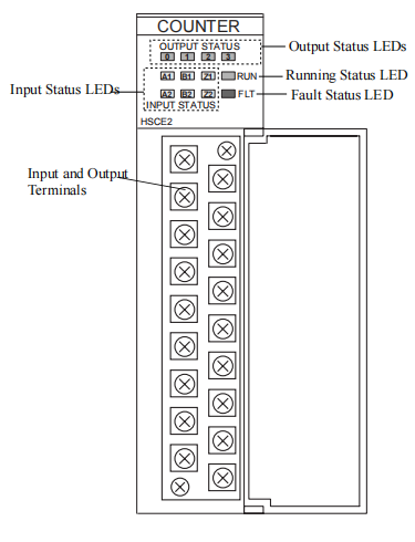
Hardware Features
The module’s hardware features are illustrated below.

Installing the Module
1. Make sure your SLC power supply has adequate reserve current capacity.
The module requires 250 mA at +5V dc.
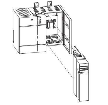
2. Align the full-sized circuit board with the chassis card guide as shown below.
The first slot of the first chassis is reserved for the processor.
3. Slide the module into the chassis until the top and bottom latches catch.
To remove the module, press the release clips at the top and bottom of the module and slide it out.
4. Cover all unused card slots with the Card Slot Filler, catalog number 1746-N2.

Important Wiring Considerations
Use the following guidelines when planning the system wiring for the module:
• Install the SLC 500 system in a NEMA-rated enclosure.
• Disconnect power to the SLC processor and the module before wiring.
• Make sure the system is properly grounded.
• Group this module and low-voltage DC modules away from AC I/O or
high-voltage DC modules.
• Shielded cable is required for high-speed input signals A, B, and Z. Use
individually shielded, twisted pair cable lengths up to 300 m (1000 ft.).
• Shields should be grounded only at one end. Ground the shield wire outside
the module at the chassis mounting screw. Connect the shield at the encoder
end only if the housing is isolated from the motor and ground.
• If you have a junction in the cable, treat the shields as a conductor at all
junctions. Do not ground them to the junction box.
Considerations for Reducing Noise
In high noise environments, the 1746-HSCE2 inputs may accept “false” pulses,
particularly when using low frequency input signals with slowly sloping pulse
edges. To minimize the effects of high frequency noise on low frequency signals,
the user can do the following:
• Identify and remove noise sources.
• Route 1746-HSCE2 input cabling away from noise sources.
• Install low pass filters on input signals. Filter values are dependent on the
application and can be determined empirically.
• Use devices which output differential signals, like differential encoders, to
minimize the possibility that a noise source will cause a false input.

Electronic Protection
The electronic protection of the 1746-HSCE2 has been designed to provide
protection for the module from short-circuit and overload current conditions. The
protection is based on a thermal cut-out principle. In the event of a short circuit or
overload current condition on an output channel, all channels turn off within
milliseconds after the thermal cut-out temperature has been reached.
IMPORTANT
The module does not provide protection against reverse
polarity wiring or wiring to AC power sources. Electronic
protection is not intended to replace fuses, circuit breakers, or
other code-required wiring protection devices.
Auto Reset Operation
IMPORTANT
1746-HSCE2 outputs perform auto-reset under overload
conditions. When an output channel overload occurs as
described above, all channels turn off within milliseconds
after the thermal cut-out temperature has been reached. While
the overcurrent condition is present, the module tries resetting
the outputs at intervals of 500 ms. If the fuse cools below the
thermal cut-out temperature, all outputs will auto-reset and
resume control of their external loads as directed by the
module until the thermal cut-out temperature is again reached.
Removing power from an overloaded output channel would
also allow the fuse to cool below the thermal cut-out
temperature, allowing auto-reset to occur when power is
restored. The output channel then operates as directed by the
module until the thermal cut-out temperature is again reached.
To avoid auto-reset of output channels under overload
conditions, monitor the fuse blown status bit (FB1) in the
module’s status file and latch the output off when an
overcurrent condition occurs. An external mechanical fuse
can also be used to open an output circuit when it is
- Informations
- Industry information
- ABB
- A-B
- GE
- MOOG
- NI
- YOKOGAWA
- FOXBORO
- BENTLY
- B&R
- UNIOP
- Abaco
- KONGSBERG
- Triconex
- HITACHI
- Emerson
- Honeywell
- Motorola
- Omron
- CTI
- Woodward
- Eaton
- EPRO
- KOLLMORGEN
- SST
- Scanlab
- Reliance
- DFI
- Prosoft
- Rexroth
- Vibro-Meter
- Mitsubishi Power
- Parker
- GEA
- MAN
- ALSTOM
- SBS
- PCH Engineering
- ZYGO
- HIMA
- BIFFI
- Advantest
- KUKA
- Full-V
- DEIF
- IBA
- Euresys
- Vishay
- Meggitt
- Aerotech
- Merlin Embedded
- Baker Hughes
- Horner
- Control Wave
- Schneider
- Siemens
- KEBA
- TEWS
- MERSEN
- Panasonic
- Ingersoll Rand
- Watlow
- Johnson Controls
- irtec
- Baldor
-
ABB CP555 1SBP260179R1001 Industrial Control Panel
-
ABB 500BIM01 1MRB160024R0002 Binary Input Signal Interface Module
-
ABB 500BIO01 1MRB150005R0001 1MRB200060/E Digital Input Output Interface Module
-
ABB 500BIO01 1MRB150005R1/J Binary Input Output Interface Module
-
ABB 500BOM01 1MRB150023R0002 Bus Organization Module
-
ABB 500CIM05 1MRB150077R1/B Communication Interface Module
-
ABB 500CMP04 HE401314/0001 1MRB150051R1 Communication Management Processor Module
-
ABB 500CPU03 1HDF700003R5122 Central Processing Unit Modul
-
ABB 500CPU05 1MRB150081R1/E Central Processing Unit Module
-
ABB 500CSP04 HE401314/0002 1MRB150051R2 Communication System Processor Module
-
ABB 500MBA02 1MRB150003R000/B Memory Backup Module
-
ABB 500MBA01 1MRB150003R0002 1MRB200053/L Memory Backup Module
-
ABB 500MBA02 1MRB150003R0003 1MRB200053/M
-
ABB 500MTM02 1MRB150020R1102 1HDF 930512 X010 Measurement and Termination Module
-
ABB 500MTM02 1MRK001967-AA 1HDF 930512 X010 Measurement and Termination Module
-
ABB 500PB101 1MRB178009R0001 1MRB200064/C Processor Bus Module
-
ABB 500PSM02 1MRB150015R1 AD-272.100.20-01 AZ:C Power Supply Module
-
ABB 500PSM03 1MRB 150038 R1 894-030375D 136-011100H Power Supply Module
-
ABB 500SCM01 1MRB200059/C 1MRB15004R0001 Serial Communication Module
-
ABB 500SCM01 1MRE450004R1 Serial Communication Module
-
ABB 500TRM02 1MRB150011R0001 Temperature Relay Module
-
ABB 500TRM02 1MRB150011R1 Temperature Relay Module
-
ABB 500TTM02 1MB150021R01161HF930712X010 Temperature Transmitter Module
-
YOKOGAWA PW484 24 V DC Input Power Supply Module
-
YOKOGAWA PW482 220-240 V AC Input Power Supply Module
-
YOKOGAWA PW481 100-120 V AC Input Power Supply Module
-
CTI 2532 - 16-point Form-A Relay Output Module
-
CTI 2573-MOD - Serial Interface Adapter w/MODBUS
-
CTI 2572-B - Fast Ethernet TCP/IP Adapter
-
CTI 2513 - 24VDC Power Supply
-
CTI 2512-A - 75W AC PS w/redundancy support
-
CTI 2512 - 75-watt AC Power Supply
-
CTI 2500-RIO-B - RS485 RBC
-
CTI 2500-RBC - Profibus RBC
-
CTI 2500-R11-A - Eleven-slot redundant base
-
CTI 2500P-R8 - Eight-slot base
-
CTI 2500P-ACP1 Application Coprocessor module
-
CTI 2500P-J750 Janus PAC with 3MB Project Memory
-
CTI 2500-C200 CPU with 256K User Memory
-
B&R 8LSA46.R0045D000-0 Servo Motor
-
B&R 5PC910SX02-00 REV:K6 Power Supply Module
-
B&R 7EX470.50-1 2003 CAN bus controller
-
B&R 5AC600.GPI0-K05 slot interface module
-
B&R 5AC600.FLAP-K11 slot interface module
-
B&R 5PP120.1214-37A Power Panel
-
B&R 5AP1130.156C-000 Automation Panel
-
B&R 3IF661.9 2005 interface module
-
B&R 5DLSD3.1000-00 Automation Panel link module
-
B&R 5AP933.215C-00 Automation Panel
-
B&R 8AC110.60-2 ACOPOS plug-in module
-
B&R 8AC120.60-1 ACOPOS plug-in module
-
B&R 5AP920.1505-01 Automation Panel
-
B&R 7DO135.70 Digital Output Module
-
B&R 7DI140.70 Digital Input Module
-
B&R 7AO352.70 Analog Output Module
-
B&R AO352 Analog Output Module
-
B&R AT664 Analog Input Module
-
B&R AT664 Analog Input Module
-
B&R DO135 Digital Output Module
-
B&R 4P3040.00-490 Power Panel
-
B&R X20CP1486 high-performance CPU
-
B&R 5CFCRD.0064-03 CompactFlash 64 MB Western Digital (SLC)
-
B&R X20BM15 Bus Module
-
B&R MDA115-0 MULTI digital output module
-
B&R MCGE31-0 Power Supply Module
-
B&R HCMCO3MC-1A Network Controller Module
-
B&R HCMARC-0CT Network Controller Module
-
B&R ECPP40-01 Industrial Controller Module
-
B&R ECPNC3-1 11150168481 Process Control Module
-
B&R 2DS100.60-1 PLC Module/Rack
-
B&R 2CP100.60-1 PLC Module/Rack
-
B&R 2BM100.9 Analog Input Module
-
Honeywell FC-TSAI-1620M Field termination assembly module
-
J-MHM10 YAMATAKE HONEYWELL INTERFACE MODULE
-
Honeywell 51401437-301 Dual Channel Safety Relay Module
-
Honeywell 51404203-002 Universal Board
-
Foxboro Suite™ DCSandI/A Series® Tools Q0301JL
-
HIMA F7130A 984713060 specialized power supply module
-
HIMA H41q-HS B4237-1 997104237 control module
-
HIMA K9202 996920202 high-reliability relay module
-
HIMA H4135 992413502 Safety Relay Module
-
HIMA Z7149 Digital Output Module
-
HIMA H51q-H B5233-2 997235233 control module
-
HIMA X-DO1201 985210204 Digital Output Module
-
HIMA X-BLK01 632590802 Blanking Module for I/O Slots
-
HIMA X-DI1601 985210222 Digital Input Module
-
HIMA LM002_MAX 985020002 Digital Output Module
-
HIMA X-FAN1003 993201013 | Redundant Cooling Fan Module
-
HIMA K9203 996920302 Communication Adapter
-
H51q-HRS B5233-2 997205233 HIMA safety system module
-
HIMA K9203A 996920360 Cooling Fan Module
-
HIMA H51q-HS B5233-1 997105233 Central Rack System
-
HIMA F8621A 984862160 Communication Module
-
HIMA F7131 981713102 High-Current DC/DC Power Supply Module
-
HIMA ELOPII Industrial Control Module
-
HIMA F8620/11 Central Processing Unit
-
X-FAN 18 03 HIMA substrate fan
-
HIMA K9202B Industrial Safety Module
-
HIMA BV7046-4 Digital Output Module
-
F30 010 20 OS-REV.V6.46/V11.28 HIMatrix Safety-Related Controller
-
HIMA F2DO801 Digital Output Module
-
HIMATRIX F3001020 | HIMA Safety-Related Controller
-
HIMA Z7116/3236/C5 Connection Module
-
HIMA F3DIO20/802 982200442 Digital Input Module
-
HIMA 80105 984080105 versatile communication module
-
HIMA X-DO2401 985210203 Digital Output Module
-
HIMA X-DI3201 985210201 Digital input module
-
F8651X HIMA Analog Input Module
-
HIMA F8650E CPU Module Brand
-
HIMA safety-related F2DO1601 remote I/O
-
HIMA F-PWR02 power buffer module
-
HIMA EABT3 B9302 997009302 Communication Module
-
HIMA K1412B 996141261 H51q-HRS B5233-2 997205233 System Rack Assembly
-
HIMA K7214 996721402 Power Distribution Module
-
HIMA TM202-A00-B00-C00-D00-E00-G00 Controller Module
-
HIMA TM521-A02-B00-C02-D00-E01-G00-I0-M1 Controller Module
-
HIMA TM591-B00-G00 Controller Module
-
HIMA KFD2-STC4-Ex1 transmitter power supply
-
HIMA KFD2-STC4-Ex1 transmitter power supply
-
HIMA SB3073-EX isolation safety barrier
-
HIMA KFD2-VR4-Ex1.26 voltage repeater
-
HIMA F3236 984323602 | sensor | Safety relay
-
HIMA F8652E 984865264 | Safety Controller Module
-
HIMA F8627 984862702 Safety-Related CPU module
-
HIMA Z7130 Safety Instrumented System
-
Hima H6200A Transmitter Circuit
-
Foxboro 9720052-XXX Field Termination Guide for Tricon Systems
-
Foxboro 9791007-XXX Technical Product Guide for Tricon Systems


wechat/whatsapp:
Email: kongjiangauto@163.com
-
ABB CP555 1SBP260179R1001 Industrial Control Panel
-
ABB 500BIM01 1MRB160024R0002 Binary Input Signal Interface Module
-
ABB 500BIO01 1MRB150005R0001 1MRB200060/E Digital Input Output Interface Module
-
ABB 500BIO01 1MRB150005R1/J Binary Input Output Interface Module
-
ABB 500BOM01 1MRB150023R0002 Bus Organization Module
Copyright © 2009 - 2024 Cld , All Rights Reserved K-JIANG All rights reserved
