
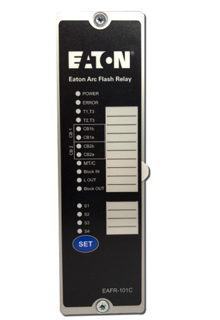
Eaton EAFR-101C arc point sensor relay
Introduction
Read these instructions carefully and inspect the equipment to
become familiar with it before trying to install, operate, service, or
maintain it .
Electrical equipment should be installed, operated, serviced, and
maintained only by qualified personnel . Local safety regulations
should be followed . No responsibility is assumed by Eaton for any
consequences arising out of the use of this material .
Eaton reserves right to changes without further notice .
Abbreviations
CB – Circuit breaker
CBFP – Circuit breaker failure protection
EMC – Electromagnetic compatibility
EPROM – Erasable programmable read only memory
HW – Hardware
LED – Light emitting diode
LV – Low voltage
ms – Millisecond
MV – Medium voltage
NC – Normally closed
NO – Normally open
PMSG – Permanent magnet synchronous generator
Rx – Receiver
SF – System failure
SW – Software
Tx – Transceiver
uP2– Microprocessor
General
The Eaton arc flash relay 101C (EAFR-101C) is a sophisticated
micro-processor based arc flash protection relay including complete
self-supervision functionality . It is designed to minimize the damage
caused by an arcing fault (arc flash) by sensing light from the point
sensor and acting to trip the circuit breaker sourcing the fault
current . The EAFR-101C complete system self-supervision function
provides the highest level of dependability by continuously monitor
ing all internal system functions along with external connections .
The EAFR-101C is designed according to the latest protection relay
standards and is therefore suitable for installations in rough environ
ments, such as utility, traditional or renewable power plants, off
shore, marine, oil and gas, mining, steel, or any other heavy industry
applications . It is also well suited for commercial and institutional
electrical systems . The EAFR-101C is suitable for either medium
voltage or low voltage switchgear and motor control center applica
tions in both new and retrofit installations .
EAFR-101C features
The EAFR-101C is a multipurpose arc flash protection relay that can
receive light from four different channels of light point sensors and
can be applied for variety of applications . The EAFR-101C can be
used as a stand-alone relay or as part of a more complex arc protec
tion system through the binary bus .
Main features of EAFR-101C:
• (110-220) Vac / (125-250) Vdc auxiliary power supply;
• (18-72) Vdc optional power supply;
• Four arc point sensor channels (S1. S2. S3. and S4);
• Six binary inputs (BI1. BI2. BI3. BI4. BI5. and BI6) nominal voltage
of 24 Vdc;
• Three normally open trip relay outputs with direct trip circuit rated
contacts (T1. T2. and T3);
• One normally open electronic lock-out trip relay with direct trip
circuit rated contacts (T2);
• Two 24 Vdc binary outputs (BO1 and BO2);
• One system failure relay, form C output (SF);
• 16 indication LEDs; and
• One push-button (SET)
Operation and configuration
LED indicator functions
The EAFR-101C contains 16 indication LEDs . A user definable text
pocket can be slid in under the label for identifying each LED func
tion (except POWER and ERROR LEDs) . LEDs are located at the
front plate of the relay for clear viewing without a need for opening
doors .
During power up, the relay performs an LED test . All LEDs are
turned on for two seconds and then off . Only the blue POWER LED
will remain on . After powered up, the relay goes into protection
mode in 50 ms even while the LED test is being performed .
During normal operation, the blue power LED is ON, as are any CB
open/close status LED’s for connected CB’s .
The sensor LEDs are off during the inactive condition . If a point arc
sensor is activated, the corresponding sensor channel LED will turn
on if the activation is longer than 1 .5 ms . The sensor LED activation
function is latched (steady light) . To clear the LED, the “SET” button
should be pressed .
In case of a loose sensor wire and binary input wires or configura
tion mismatch (new sensor attached without running auto-configu
ration system setup (see Section 3 .3 .1) situation, the corresponding
LED for that sensor will start flashing and the ERROR LED will
activate .
The Binary I/O LEDs indicate the I/O-line status . If any of the lines
become active for more than 1 .5 ms, the corresponding LED will
turn on (latch) .
In a trip situation, the corresponding trip LED will turn on . Trip
outputs are controlled by the dipswitch settings (see Section 3 .5) .
All activation and trip indication LEDs are latched, even if the
dipswitch setting is in the non-latched mode . They have to be
cleared by pushing the “SET” button .
LED indications are stored in non-volatile EPROM memory for iden
tifying the trip information in case the auxiliary power is lost . When
re-powering the relay after power supply loss, the actual LED status
can be visualized from the front of the relay
- Informations
- Industry information
- Others
- Autronica
- ABB
- A-B
- GE
- MOOG
- NI
- YOKOGAWA
- FOXBORO
- BENTLY
- B&R
- UNIOP
- KONGSBERG
- Triconex
- HITACHI
- Emerson
- Honeywell
- Motorola
- Omron
- CTI
- Woodward
- Eaton
- EPRO
- KOLLMORGEN
- SST
- Scanlab
- Reliance
- Prosoft
- Rexroth
- Vibro-Meter
- Mitsubishi Power
- Parker
- ALSTOM
- PCH Engineering
- SBS
- HIMA
- BIFFI
- Advantest
- KUKA
- DEIF
- IBA
- Euresys
- Meggitt
- Aerotech
- Merlin Embedded
- Baker Hughes
- Horner
- Control Wave
- Siemens
- Schneider
- KEBA
- TEWS
- Ingersoll Rand
- MERSEN
- Panasonic
- Watlow
- Johnson Controls
- Alfa Laval
- Bachmann
- Hirschmann
- ZYGO
- GUTOR
- ICS TRIPLEX
- OEMAX
- Beckhoff
- Nidec
- TMEIC
- LENZE
- BAUMULLER
-
Kollmorgen AKT2G-ENC-180-000 1-Channel Incremental Encoder Interface
-
Kollmorgen AKT2G-ENC-190-000 Incremental Encoder Interface with Differential Input
-
Kollmorgen AKT2G-AT-425-000 4 Ch Analog Outputs 0-10 and -10 to +10 Vdc
-
Kollmorgen AKT2G-AT-410-000 4 Ch Analog Outputs 0-10 and -10 to +10 Vdc
-
Kollmorgen AKT2G-SDO-004-000 4-channel digital output terminal, Safety
-
Kollmorgen AKT2G-DT-008-000 8 Ch Digital Output 0.5A
-
Kollmorgen AKT2G-SDI-004 4-channel digital input terminal, Safety
-
Kollmorgen AKT2G-DNH-008-000 8 Ch Digital Inputs
-
Kollmorgen AKT2G-DN-008-000 8 Ch Digital Inputs
-
Kollmorgen AKT2G-DN-002-000 2 Ch Digital Input
-
Kollmorgen AKT2G-AN-400-000 4-channel thermocouple input terminal
-
Kollmorgen AKT2G-AN-240-000 2-channel input terminal for resistance sensors
-
Kollmorgen AKT2G-AN-430-000 4-channel analog input, parameterizable
-
Beckhoff EK1818 | EtherCAT Coupler with integrated digital inputs/outputs
-
Beckhoff EK1561 | 1-port EtherCAT plastic optical fiber junction
-
Beckhoff EK1541 | EtherCAT Coupler with ID switch, plastic optical fiber
-
Beckhoff EK1521 | 1-port EtherCAT fiber-optic junction
-
Beckhoff EK1501-0010 | EtherCAT Coupler with ID switch, single-mode fiber optic
-
Beckhoff EK1501 | EtherCAT Coupler with ID switch, multi-mode fiber optic
-
Beckhoff EK1400 | EtherCAT G Coupler
-
Beckhoff EK1322 | 2-port EtherCAT P junction with feed-in
-
Beckhoff EK1310 | 1-port EtherCAT P extension with feed-in
-
Beckhoff EK1300 | EtherCAT P coupler
-
Beckhoff EK1122-0080 | 2-port EtherCAT junction, Fast Hot Connect
-
Beckhoff EK1122-0008 | 2-port EtherCAT junction with M8 connection
-
Beckhoff EK1122 | 2-port EtherCAT junction
-
Beckhoff EK1121-0010 | 1-port EtherCAT junction, Extended Distance
-
Beckhoff EK1110-0043 | EtherCAT EJ coupler, CX and ELterminal connection
-
Beckhoff EK1110-0008 | EtherCAT extension with M8 connection
-
Beckhoff EC1110 | EtherCAT Terminal extension, RJ45, angled, push-in
-
Beckhoff CU8130-0240 | UPS modul, battery-backed
-
Beckhoff CU8130-0120 | UPS module, battery-backed
-
Beckhoff CU8110-0120 | UPS module, capacitive
-
Beckhoff CU8110-0060 | UPS module, capacitive
-
Beckhoff CX2062 | Embedded PC with Intel® Xeon® D-1548
-
Beckhoff CX2042 | Embedded PC with Intel® Xeon® D-1527
-
Beckhoff CX2500-0021 | Audio interface for CX20x3
-
Beckhoff CX2100-0914 | Power supply unit for external battery pack for CX20x3 and CX2042
-
Beckhoff CX2100-0024 | 200 W power supply module
-
Beckhoff CX2100-0022 | 100 W power supply module
-
Beckhoff CX2100-0014 | Power supply unit for CX20xx, 130 W
-
Beckhoff CX2100-0004 | Power supply unit for CX2033, 45 W
-
Beckhoff CX2043 | Embedded PC with AMD Ryzen™ V1807B
-
Beckhoff CX2033 | Embedded PC with AMD Ryzen™ V1202B
-
BAUMULLER b maXX 5500 – The servo drive for higher output ratings
-
BAUMULLER b maXX 3000 Servo Controller BM3401-LIFBO-ACOOOCB-G-02-O-02
-
GE PCM Regulator for EX2100e Power Conversion Module 151X1235DB15SA1
-
Kollmorgen PCMM2G Essentials programmable motion controller
-
Kollmorgen Automation Suite™ Cables
-
LENZE g500-B + m500 bevel geared motors
-
LENZE g500-S + m500 shaft-mounted helical geared motors
-
LENZE g500-H + m500 helical geared motors
-
LENZE OCU series motor controllers
-
LENZE SMD frequency inverters
-
LENZE 8200 vector frequency inverters
-
LENZE 9300 vector frequency inverters
-
LENZE 9300 servo inverters
-
LENZE ECS servo inverters
-
LENZE MC series frequency inverters
-
LENZE 8400 BaseLine frequency inverters
-
LENZE SCF Frequency inverter in IP20 with V/f Control
-
LENZE SCM/SCL Frequency inverter in IP20 with V/f Control
-
LENZE 940 Servo inverter for controlled, dynamic motion
-
LENZE 8400 TopLine frequency inverter
-
LENZE 8400 HighLine frequency inverter
-
LENZE 8400 StateLine frequency inverter
-
LENZE 9400 HighLine servo inverter
-
LENZE i950 cabinet servo inverter
-
LENZE i750 cabinet servo inverter
-
LENZE i700 cabinet servo inverter
-
LENZE SMVector IP65 frequency inverter
-
LENZE SMVector IP31 frequency inverter
-
LENZE 8400 motec frequency inverter
-
LENZE i650 motec frequency inverter
-
LENZE i550 motec frequency inverter
-
LENZE 8400 protec frequency inverter
-
LENZE i550 protec frequency inverter
-
LENZE ECSEA048C4B Axis Module
-
Beckhoff CX5630 | Embedded PC with AMD Ryzen™ R1505G
-
Beckhoff CX5620 | Embedded PC with AMD Ryzen™ R1102G
-
Beckhoff CX5340 | Embedded PC with Intel Atom® x6425RE
-
Beckhoff CX5330 | Embedded PC with Intel Atom® x6214RE
-
Beckhoff CX2500-M510 | Fieldbus master module
-
Beckhoff CX2500-M310 | Fieldbus master module
-
Beckhoff CX2500-B510 | Fieldbus slave module
-
Beckhoff CX2500-B310 | Fieldbus slave module
-
Beckhoff CX2500-0070 | USB 3.0 module for CX20xx, CX52xx, CX53x0, CX56x0
-
Beckhoff CX2500-0062 | 2.5 Gbit Ethernet module for CX20xx, CX52x0, CX53x0, CX56x0
-
Beckhoff CX2500-1061 | Power over Ethernet module for CX20xx, CX52x0, CX53x0, CX56x0
-
Beckhoff CX2500-0061 | Power over Ethernet module for CX20xx, CX52x0, CX53x0, CX56x0
-
Beckhoff CX2500-1060 | Ethernet module for CX20xx, CX52x0, CX53x0, CX56x0
-
Beckhoff CX2500-0060 | Ethernet module for CX20xx, CX52x0, CX53x0, CX56x0
-
Beckhoff CX2500-0031 | Serial Interface RS485/RS422 for CX20xx, CX52x0, CX53x0, CX56x0
-
Beckhoff CX2500-0030 | Serial Interface RS232 for CX20xx, CX52x0, CX53x0, CX56x0
-
Beckhoff CX5240 | Embedded PC with Intel Atom® x5-E3940
-
Beckhoff CX5230 | Embedded PC with Intel Atom® x5-E3930
-
Beckhoff CX5140 | Embedded PC with Intel Atom® E3845
-
Beckhoff CX5130 | Embedded PC with Intel Atom® E3827
-
Beckhoff CX5120 | Embedded PC with Intel Atom® E3815
-
Beckhoff CX9020 | Embedded PC with Arm® Cortex®-A8
-
Beckhoff CX8290 | Embedded PC with Arm® Cortex®-A53 and 2-port Ethernet switch
-
Beckhoff CX8280 | Embedded PC with Arm® Cortex®-A53 and RS232/RS485
-
Beckhoff CX8210 | Embedded PC with Arm® Cortex®-A53 and EtherCAT slave
-
Beckhoff CX8200 | Embedded PC with Arm® Cortex®-A53
-
Beckhoff CX8191 | Embedded PC with Arm® Cortex®-A9 and BACnet/IP
-
Beckhoff CX8190 | Embedded PC with Arm® Cortex®-A9 and 2-port Ethernet switch
-
Beckhoff CX8180 | Embedded PC with Arm® Cortex®-A9 and RS232/RS485
-
Beckhoff CX8110 | Embedded PC with Arm® Cortex®-A9 and EtherCAT slave
-
Beckhoff CX8095 | Embedded PC with Arm9™ and EtherNet/IP™ adapter
-
Beckhoff CX8093 | Embedded PC with Arm9™ and PROFINET device
-
Beckhoff CX8091 | Embedded PC with Arm9™ and BACnet/IP or OPC UA
-
Beckhoff CX8090 | Embedded PC with Arm9™ and 2-port Ethernet switch
-
Beckhoff CX8080 | Embedded PC with Arm9™ and RS232/RS485
-
Beckhoff CX8051 | Embedded PC with Arm9™ and CANopen slave
-
Beckhoff CX8050 | Embedded PC with Arm9™ and CANopen master
-
Beckhoff CX8031 | Embedded PC with Arm9™ and PROFIBUS slave
-
Beckhoff CX8030 | Embedded PC with Arm9™ and PROFIBUS master
-
Beckhoff CX8010 | Embedded PC with Arm9™ and EtherCAT slave
-
Beckhoff CX7293 | Embedded PC with Arm® Cortex®-A9, PROFINET RT device and integrated I/Os
-
Beckhoff CX7291 | Embedded PC with Arm® Cortex®-A9, BACnet/IP and integrated I/Os
-
Beckhoff CX7080 | Embedded PC with Arm® Cortex®-M7, RS232/RS485 and integrated I/Os
-
Beckhoff CX7051 | Embedded PC with Arm® Cortex®-M7, CANopen responder (slave) and integrated I/Os
-
Beckhoff CX7050 | Embedded PC with Arm® Cortex®-M7, CANopen commander (master) and integrated I/Os
-
Beckhoff CX7031 | Embedded PC with Arm® Cortex®-M7, PROFIBUS slave and integrated I/Os
-
Beckhoff CX7000 | Embedded PC with Arm® Cortex®-M7 and integrated I/Os
-
LENZE i510 protec frequency inverter
-
LENZE i550 cabinet frequency inverter
-
LENZE i510 cabinet frequency inverter


wechat/whatsapp:
+86-181-44100-983
Email: kongjiangauto@163.com
-
GE PCM Regulator for EX2100e Power Conversion Module 151X1235DB15SA1
-
3BSE006503R1 PFSA 140, Roll Supply Unit
-
ABB PFSC230 cable set 25m for DTU
-
GE ENERGY HYDRAN H201Ci-1 One-Channel Controller
-
ABB 3BUS208720-001 POWER SIGNAL INTERCONNECT
Copyright © 2009 - 2024 Cld , All Rights Reserved K-JIANG All rights reserved